Table of Contents
Advertisement
Quick Links
Brand:
Crompton
Type:
VFD Drive
Models:
Emotron VSR Series
CONNECTION DIAGRAM
The communication terminals (RS485) are located at the bottom of the drive. And there are two connection
terminals on the configuration circuit board: RS485 A/B terminal blocks.
1. Press and hold in the tabs on each side of the cover.
Pull the cover up to release keypad.
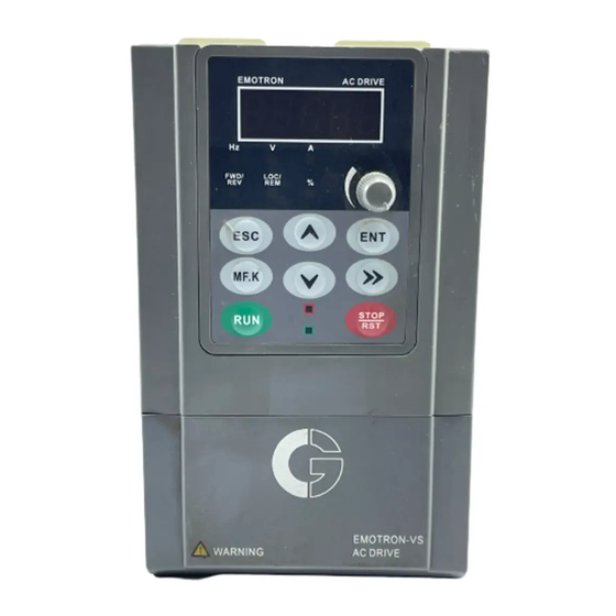
2. Locate the RS485 terminal (communication port 1)
as shown in Figure C1.
3. Please make the connections from the Terminal Block of Crompton RS485 chipset to TrackSo IoT Gateway
as mentioned in the Table – CT1
4. Proivde 12-24V DC Supply to TrackSo at Pin no. 1& 2.
Table CT1 – Crompton RS485 chip connections with TrackSo IoT Gateway
TRACKSO INSTALLATION GUIDE FOR CROMPTON VFD
Figure C1– Communication Port of Crompton VSR Series
Crompton RS485
Communication Card pin no.
& Assignment
485+
485-
TrackSo Pin No. &
Assignment
3
DATA+
4
DATA-
Advertisement
Table of Contents

Related Manuals for Crompton Emotron VSR Series


Summary of Contents for Crompton Emotron VSR Series
- Page 1 DATA- as shown in Figure C1. 3. Please make the connections from the Terminal Block of Crompton RS485 chipset to TrackSo IoT Gateway as mentioned in the Table – CT1 4. Proivde 12-24V DC Supply to TrackSo at Pin no. 1& 2.
- Page 2 DEFAULT CONFIGURATION IN TRACKSO IOT GATEW AY Inverter ID: 1, 2, 3, 4 …. Continuous numbering starting with 1, (Range: 1 to 247) Baud Rate: 9600 (Default) (Values: 9600, 19200, 38400) Data Bits: 8 Stop Bit: 1 Parity: None CONFIGURATION AT THE AC DRIVE END How to operate Digital Keyboard SETTING THE BAUD RATE This parameter is used to set the transmission speed between the RS485 master (PLC, PC, etc.) and AC motor...
- Page 3 1: Even parity check, data format (1-8-E-1) 2: Odd Parity check, data format (1-8-O-1) 0H.01 Data Format 3: No check, data format(1-8-N-1) ~ all for RTU The above details are mentioned in the Installation & Operation Manual for Crompton VFD.
- Page 4 TRACKSO WORKING 1. Insure correct connections as detailed in the installation guide. 2. Insert the SIM card. 3. Switch on the power to the TrackSo device. (Minimum 12V/1A input is required) 4. Power LED (Red) of TrackSo IoT gateway glows and stays ON. NOTE: TrackSo IoT Gateway will only be able to send data if the GPRS network is available at the installed location.
- Page 5 5. To check the exact network status send the following message to mobile number of the device SMS Command= *2222#<Stat.gsm> IMEI IMEI No. of the data logger (Device Key) Network SIGN Signal Strength out of 31 GPRS CONT- connected , NC- not connected Connected to TrackSo Server or not CONT- connected, NC- not connected no.
- Page 6 9. If the state remains Not receiveing for more than 10 minutes, click on your email ID at the top right of the screen and click on ‘Event Ingestion Logs’ in the dropdown. 10. Check if there is some log generated at the time of installation of the TrackSo IoT Gateway device. a.
Need help?
Do you have a question about the Emotron VSR Series and is the answer not in the manual?
Questions and answers