Table of Contents
Advertisement
Quick Links
Advertisement
Table of Contents

Subscribe to Our Youtube Channel
Related Manuals for Crompton Tyco Electronics SWITCHBOARD INTEGRA 1540


Summary of Contents for Crompton Tyco Electronics SWITCHBOARD INTEGRA 1540
- Page 1 Energy Division http://energy.tycoelectronics.com Installation and Operating Instructions SWITCHBOARD INTEGRA 1540 Tyco Electronics UK Limited Crompton Instruments Freebournes Road, Witham, Essex, CM8 3AH, UK Tel: +44 1376 509 509 Fax: +44 1376 509 511...
- Page 2 Installation & Operating Instructions Models INT - 1543 and INT - 1544 Crompton Instruments Freebournes Road Witham Essex CM8 3AH England Tel: +44 (0) 1376 509 509 Fax: +44 (0) 1376 509 511 E-Mail: crompton.info@tycoelectronics.com Crompton Instruments 1540 MANUAL Issue 1 11/2002...
-
Page 3: Table Of Contents
Contents Page Introduction 2 Installation Display EMC Installation Requirements Case Dimension and Panel Cut-Out 2.3.1 Model INT-1540 Wiring Auxiliary Supply Fusing Earth/Ground Connections 3 Connection Diagrams View of Terminals USA Style European Style 4 Integra 1540 Display Screens Screen 1 – System Screen INT-1540 Screen 2 –... -
Page 4: Introduction
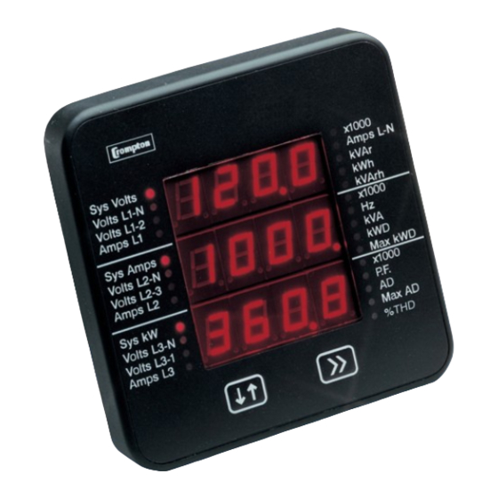
1 Introduction The Crompton Switchboard 1540 is a panel mounted self contained measuring, display and communication device. This system will measure display and communicate up to 31 electrical parameters, integrating high accuracy measurement technology with the simplicity and visibility of 7 segment LED displays. -
Page 5: Installation
A pulsed relay output, representing kW.h, with selectable pulse width, and an RS485 Modbus output (see Section 4 Integra 1540 Display Screens) are available as optional features. Connections for both are via screw clamp terminals. 2 Installation 2.1 Display The Switchboard Integra 1540 may be mounted in a panel of any thickness up to a maximum of 0.47”. -
Page 6: Case Dimension And Panel Cut-Out
2.3 Case Dimension and Panel Cut-Out 2.3.1 Model INT-1540 Model ANSI DIM A 3.54” (90.0mm) 3.37” (85.7mm) DIM B 3.90” (99.0mm) 3.98” (101.2mm) DIM X 3.54” (90.0mm) 3.37” (85.7mm) DIM Y 3.98” (101.2mm) 4.06” (103.0mm) DIM Z Ø0.22” (5.5mm) Ø0.31” (7.87mm) -
Page 7: Wiring
2.4 Wiring Input connections are made to screw clamp terminals. Choice of cable should meet local regulations. Terminals for both current and voltage inputs will accept up to 3mm x 2 diameter cables or ring lugs suitable for 6-32 screws. Output connections are made directly to the screw clamp style terminals. -
Page 8: Connection Diagrams
3 Connection Diagrams 3.1 View of Terminals 3.2 USA Style Importing Connections Exporting Connections... -
Page 9: European Style
3.3 European Style IMPORTING CONNECTIONS EXPORTING CONNECTIONS... -
Page 10: Integra 1540 Display Screens
4 Integra 1540 Display Screens 4.1 Screen 1 – System Screen INT-1540 The system screen is the default display. It appears when the unit is energised. System Average Voltage (Volts) {Line to Line for 3 wire systems, Line to Neutral for 4 wire systems}. System Average Line Current (Amps). -
Page 11: Screen 4 - Line To Neutral Voltage %Thd
4.4 Screen 4 – Line to Neutral Voltage %THD Three phase, four wire systems only. %THD of Line 1 Voltage to Neutral. %THD of Line 2 Voltage to Neutral. %THD of Line 3 Voltage to Neutral. Key >> brings up Screen 7, Line Currents. 4.5 Screen 5 –... -
Page 12: Screen 7 - Line Currents
4.7 Screen 7 – Line Currents Line 1 Current (Amps). Line 2 Current (Amps). Line 3 Current (Amps). Key >> brings up Screen 8, Line Currents %THD. 4.8 Screen 8 – Line Currents %THD Line 1 Current %THD. Line 2 Current %THD. Line 3 Current %THD. -
Page 13: Screen 10 - Power
4.10 Screen 10 – Power Reactive Power (kVAr). Apparent Power (kVA). Active Power (kW). Key >> brings up Screen 11, Active Energy. 4.11 Screen 11– Active Energy (kW.h) Active Energy (kW.h). 7 digit reading i.e. 0001243. Key >> brings up Screen 12, Reactive Energy. 4.12 Screen 12 –... -
Page 14: Screen 13 - Active Power And Current Demands
4.13 Screen 13 – Active Power and Current Demands System Total Active Power Demand (kWD). System Total Current Demand (AD). Key >> brings up Screen 14 Active Power and Current Maximum Demands. 4.14 Screen 14 – Active Power and Current Maximum Demands Maximum System Total Active Power Demand (kWD). -
Page 15: Kw.h And Kvar.h Display Range
4.16 kW.h and kVAr.h Display Range The kW.h and kVAr.h display range is limited to 9999999. If the unit is allowed to increment beyond this value the internal count will continue to be updated, but the display will change to seven bars. -
Page 16: Programming
5 Programming The following sections comprise step by step procedures for configuring the Switchboard 1540 for the individual user requirements. To access the set-up screens press and hold the “ Adjust” and “>> Next” keys simultaneously for 5 seconds. This will take the user into the password protection entry stage. (See Section 5.1 Password Protection). - Page 17 Enter Password, second digit entered, prompt for third digit. (* Denotes that decimal point will be flashing). Use the “ Adjust” key to scroll the value of the third digit from 0 through to 9, the value will wrap from 9 round to 0. Press the “>>...
- Page 18 Password Incorrect. The unit has not accepted the password entered. Pressing the “ Adjust” key will return to the “Enter Password“ stage. Pressing the “>> Next” key exits the set-up menus and returns operation to the normal display mode. New/Change Password. (* decimal point indicates that this will be flashing).
-
Page 19: Set-Up Screens
New/Change Password, third digit entered, prompting for fourth digit. (* Denotes that decimal point will be flashing). Pressing the “ Adjust” key will scroll the value of the fourth digit from 0 through to 9, the value will wrap from 9 round to Pressing the “>>... -
Page 20: Potential Transformer Ratio Primary Value
The “Maximum Power” restriction of 360 Megawatts refers to 120% of nominal current and 120% of nominal voltage, i.e. 250 Megawatts nominal system power. When the least significant digit has been set, pressing the “>> Next” key will advance to the “Full Scale Current Confirmation”... - Page 21 Potential Transformer Digit Edit. Pressing the “ Adjust” key will scroll the value of the most significant digit from 0 through to 9 unless the presently displayed potential transformer ratio together with the full scale current value, previously set, would result in a maximum power of greater than 360 Megawatts in which case the digit range will be restricted.
-
Page 22: Demand Integration Time Edit
5.2.3 Demand Integration Time Edit This screen is used to set the time taken for maximum demand readings; the value displayed represents time in minutes. Integration periods of 8, 15, 20 or 30 minutes can be selected. Pressing the “>> Next” key accepts the present value and advances to the “Reset”... -
Page 23: Resets
5.2.4 Resets The following screens allow the user to reset the Active Energy, Demand and Maximum Demand readings individually or altogether. Note: Resetting the Demand will automatically reset the Maximum Demands (HiAd and HiPd). Reset (None). Pressing the “>> Next” key advances to the “Pulse Duration” menu. - Page 24 Reset parameter Select, (Reset Energy Variables). The user has scrolled through to the “h”(Active Energy) value. Pressing the “>>Next” key will select the value and advance to the “Reset Active Energy Confirmation” Mode. Reset Active Energy Variables Confirmation. Pressing the “ Adjust”...
-
Page 25: Pulsed Output, Pulse Duration
5.2.5 Pulsed Output, Pulse Duration This applies to the Relay Pulsed Output option only. This screen allows the user to set the duration of the relay energisation time. The displayed value represents the time in milliseconds. Pulse Duration Edit. Pressing the “>> Next” key accepts the present value and advances to the “Pulse Rate”... -
Page 26: Rs 485 Baud Rate
Pulse Rate Divisor Confirmation. This screen will only appear following an edit of the Pulse Rate Divisor. If the divisor shown is not correct, pressing “ Adjust” key will return the operation to the “Pulse Rate Divisor Edit” stage by blanking the bottom line of the display. Pressing the “>>... -
Page 27: Rs 485 Parity Selection
5.2.8 RS 485 Parity Selection This applies to the RS 485 Output option only. This screen allows the user to set the parity of the RS 485 Modbus Output. RS 485 Parity Selection. Pressing the “>> Next” key accepts the present value and advances to the “RS 485 Modbus Address”... - Page 28 Note: When the most significant digit is set to 2 the lesser significant digits must be less than or equal to 47, the digits will scroll through from 0 to 4 and 0 to 7 as appropriate. The range of the allowable addresses is 1 to 247. RS 485 Modbus Address Confirmation.
-
Page 29: Outputs
6 Outputs 6.1 Modbus‚ Implementation Integra 1540 offers the option of a RS 485 communication module for direct connection to SCADA systems using the Modbus‚ RTU protocol. The Modbus‚ protocol establishes the format for the master's query by placing into it the device address, a function code defining the requested action, any data to be sent, and an error checking field. - Page 30 Register Addresses Each parameter is held in two consecutive 16 bit registers. The following table details the 3X register address, and the values of the address bytes within the message. A tick (÷) in the column indicates that the parameter is valid for the particular wiring system. Any parameter with a cross (X) will return the value Zero (0000h).
- Page 31 Modbus Start Address Hex Address Parameter Parameter 4-wire 3-wire (Register) Number High Byte Low Byte √ √ 30237 THD Volts 2 √ √ 30239 THD Volts 3 √ √ 30241 THD Current 1 √ √ 30243 THD Current 2 √ √...
- Page 32 The Demand Time (Address 1) is used to reset the demand period. A value of zero must be written to this register to accomplish this. Writing any other value will cause an error to be returned. Any valid value sent to this register will automatically reset the Maximum Demand register.
- Page 33 Schematic showing system wiring to rear of Integra 1540...
-
Page 34: Rs485 Implementation For Johnson Controls Metasys
The Integra 1540 is a N2 Vendor device which connects directly with the Metasys N2 Bus. Each Metasys N2 Bus port can connect up to 70 units. Each Crompton device can be accessed by the full complement of Metasys Facility Management System (FMS) features, including Change-of-state (COS) monitoring, alarm notification, scheduling, trend and totalisation. - Page 35 METASYS N2 application Integra 1540 Point Mapping table Address Parameter Description Units Voltage 1 Volts Voltage 2 Volts Voltage 3 Volts Current 1 Amps Current 2 Amps Current 3 Amps Voltage average Volts Current average Amps Power (Watts) Sum Kwatts VA Sum VAr Sum kVAr...
-
Page 36: Pulsed Output
6.3 Pulsed Output This module outputs pulses at a rate proportional to the measured Active Energy (kW.h). The pulse width and pulse rate are both user definable via the set-up screens. See Sections 5.2.5 Pulsed Output, Pulse Duration and 5.2.6 Pulse Rate. The output relay provides a fully isolated, volt free contact and connection is made via screw clamp terminals, which can accept cable up to 2.5 mm... -
Page 37: Maximum Demand Calculation
7 Maximum Demand Calculation The maximum power consumption of an installation is an important measurement as most power utilities base their charges on it. Many utilities use a thermal maximum demand indicator (MDI) to measure this peak power consumption. An MDI averages the power consumed over a number of minutes, such that short surges do not give an artificially high reading. -
Page 38: Thd Calculation
8 THD Calculation The calculation used for the Total Harmonic Distortion is: THD = ((RMS of total waveform – RMS of fundamental) / RMS of total waveform) x 100 This is often referred to as THD – R The figure is limited to the range 0 to 100%. For low signal levels the noise contributions from the signal may represent a significant portion of the “RMS of total waveform”... -
Page 39: Specification
9 Specification Inputs Nominal input voltage (a.c. rms) 57 - 346V L-N 100 - 600V L-L Factory configured for each system voltage Max continuous input voltage 120% of upper value Max short duration input voltage 2* upper value (1s application repeated 10 times at 10s intervals) Nominal input voltage burden 0.2VA approx. - Page 40 Accuracy Voltage 0.4% of reading ±0.1% of range Current 0.4% of reading ±0.1% of range Neutral current 4% of range Frequency 0.15% of mid frequency Power factor 1% of Unity Active power (W) 0.9% of reading ±0.1% of range Reactive power (VAr) 1.9% of reading ±0.1% of range Apparent power (VA) 0.9% of reading ±0.1% of range...
- Page 41 Voltage Nominal ±2% Current 10 .. 100% of nominal Reactive power factor 1 .. 0.8 leading or lagging Apparent Power (VA) 10 .. 100% of nominal Voltage Nominal ±2% Current 10 .. 100% of nominal Power factor 1 .. 0.8 leading or lagging Voltage Nominal value ±2% Current...
- Page 42 Auxiliary supply voltage Nominal ±10% Auxiliary supply frequency Nominal ±10% Magnetic field of external origin 400A/m Functional ranges of measurands, and of influence quantities for measurands Values of measured quantities, components of measured quantities, and quantities which affect measurement errors to a minor degree, for which the product gives meaningful readings. Voltage 5 ..
- Page 43 Environmental Operating temperature -20 to +70°C Storage temperature -30 to +80°C Relative humidity 0 .. 95% non condensing Warm up time 1 minute Shock 30g in 3 planes Vibration 10 .. 55 Hz, 0.15mm amplitude Enclosure integrity (front face only) IP54 Harmonic distortion Max 50% THD up to 15th harmonic...
- Page 44 Tyco Electronics' standard Conditions of Sale for this product and in no case will Tyco Electronics be liable for any other incidental, indirect or consequential damages arising from the use or misuse of the products. Crompton is a trade mark.
Need help?
Do you have a question about the Tyco Electronics SWITCHBOARD INTEGRA 1540 and is the answer not in the manual?
Questions and answers