Advertisement
Quick Links
sauder.com
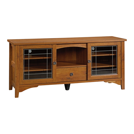
Entertainment Credenza
Rose Valley Collection | 404867
Need help? Visit Sauder.com to view video assembly tips or chat with a live rep.
Prefer the phone? Call 1-800-523-3987.
Share your journey!
Your center of
attention.
NOTE: THIS INSTRUCTION
BOOKLET CONTAINS IMPORTANT
SAFETY INFORMATION.
PLEASE READ AND KEEP FOR
FUTURE REFERENCE.
English pg 1-31
Français pg 32-35
Español pg 36-40
Lot # 370261
03/04/15
Purchased: __________________
Be sure to give us a ring before
making any returns. 1-800-523-3987
Advertisement

Related Manuals for Sauder Rose Valley 404867


Summary of Contents for Sauder Rose Valley 404867
- Page 1 Rose Valley Collection | 404867 NOTE: THIS INSTRUCTION BOOKLET CONTAINS IMPORTANT SAFETY INFORMATION. Need help? Visit Sauder.com to view video assembly tips or chat with a live rep. PLEASE READ AND KEEP FOR FUTURE REFERENCE. Prefer the phone? Call 1-800-523-3987.
- Page 2 • Check the size and weight of your TV. Compare it to the diagram below – before you begin assembly! • This Sauder unit is designed for use with televisions weighing less than 135 pounds. Never use with a TV that weighs more.
- Page 3 D107 RIGHT DRAWER SIDE (1) BOTTOM (1) VALANCE (1) D108 LEFT DRAWER SIDE (1) SHELF (1) EXTENSION BLOCK (1) D962 DRAWER BOTTOM (1) BACK (2) DRAWER FRONT (1) CENTER BACK (1) BOTTOM MOLDING (1) D108 D962 D107 www.sauder.com/services 404867 Page 3...
- Page 4 -Refer to instruction book for complete safety information. Note: This is a permanent label. Do not try to remove. Surface will be damaged. 02/ 02 2 6 9 2 3 2 269232 (Refer to Step 25 for proper location and application) Page 4 404867 www.sauder.com/services...
- Page 5 BLACK 1/2" FLAT HEAD SCREW - 8 BROWN 7/16" LARGE HEAD SCREW - 4 GOLD 5/16" FLAT HEAD SCREW - 8 NAIL - 12 SILVER 5/8" FLAT HEAD SCREW - 4 30S BLACK 1-9/16" FLAT HEAD SCREW - 4 www.sauder.com/services 404867 Page 5...
- Page 6 Assemble your unit on a carpeted fl oor or on the empty å carton to avoid scratching your unit or the fl oor. STOP To begin assembly, push a SAUDER TWIST-LOCK® å If you purchased FASTENER (EE) into the large holes in the ENDS (A and B).
- Page 7 Arrow Hole Arrow The arrow in the HIDDEN CAM must point toward the (10 used) hole in the edge of the board. Insert the metal end of the CAM DOWEL into the HIDDEN CAM. (4 used) www.sauder.com/services 404867 Page 7...
- Page 8 Step 3 Slide the BOTTOM MOLDING (V) onto the notched edge å of the BOTTOM (F). * U.S. Patent No. 5,499,886 å Notched edge Slide the BOTTOM MOLDING (V) onto the notched edge. Page 8 404867 www.sauder.com/services...
- Page 9 Lefty loosey. NOTE: The CABINET RAILS are marked "CABINET RIGHT" å and "CABINET LEFT" for easy identifi cation. Finished edge Roller end GOLD 5/16" FLAT HEAD SCREW (4 used in this step) Finished edge Roller end www.sauder.com/services 404867 Page 9...
- Page 10 S u r U n fi f a c i t h I S T - L O F A S T E N ® E R S BLACK 1-7/8" FLAT HEAD SCREW (4 used in this step) Page 10 404867 www.sauder.com/services...
- Page 11 Step 6 Turn six CAM SCREWS (8F) into the LEGS (L2 and M2). å www.sauder.com/services 404867 Page 11...
- Page 12 Step 7 Fasten the LEGS (L2 and M2) to the ENDS (A and B). å Tighten six HIDDEN CAMS. These surfaces should be almost even. Angled edge These surfaces should be almost even. Angled edge Page 12 404867 www.sauder.com/services...
- Page 13 Fasten the UPRIGHTS (C and D) to the TOP (E). Tighten å ® four TWIST-LOCK® FASTENERS. How to use the SAUDER TWIST-LOCK FASTENER 1. Insert the dowel end of the FASTENER into the hole of the adjoining part. NOTE: The dowel end of the FASTENER must remain fully inserted in the hole of the adjoining part while locking the FASTENER.
- Page 14 Fasten the VALANCE (O) to the UPRIGHTS (C and D) å and TOP (E). Use three BLACK 9/16" LARGE HEAD SCREWS (XX) through the ANGLE BRACKETS and into the UPRIGHTS and TOP. BLACK 9/16" LARGE HEAD SCREW (6 used in this step) Page 14 404867 www.sauder.com/services...
- Page 15 Tighten Risk of damage or Arrow injury. HIDDEN CAMS must be completely Arrow Maximum tightened. HIDDEN 210 degrees CAMS that are not completely tightened may loosen, and parts may separate. To Minimum completely tighten: 190 degrees www.sauder.com/services 404867 Page 15...
- Page 16 Step 11 Fasten the BOTTOM (F) to the UPRIGHTS (C and D) å and BACKS (H). Use eight BLACK 1-7/8" FLAT HEAD SCREWS (TT). BLACK 1-7/8" FLAT HEAD SCREW (8 used in this step) Page 16 404867 www.sauder.com/services...
- Page 17 I S T E R S T E N F A S i t h o ® f a c S u r - L O I S T E R S T E N F A S www.sauder.com/services 404867 Page 17...
- Page 18 Step 13 Fasten four ANGLE BRACKETS (HH) to the ENDS (A å and B) and BOTTOM (F). Use four BLACK 9/16" LARGE HEAD SCREWS (XX). BLACK 9/16" LARGE HEAD SCREW (4 used in this step) Page 18 404867 www.sauder.com/services...
- Page 19 Fasten the SKIRTS (X and Y) to the ENDS (A and B) å and BOTTOM (F). Use four BLACK 9/16" LARGE HEAD SCREWS (XX) through the ANGLE BRACKETS and into the SKIRTS. BLACK 9/16" LARGE HEAD SCREW (4 used in this step) Flat edge Flat edge www.sauder.com/services 404867 Page 19...
- Page 20 NOTE: If the MOLDINGS come up off of the SCREWS, remove them and slide å them on again. Shoulder BLACK 9/16" FLAT HEAD SCREW Apply pressure with your hands (12 used in this step) as you guide the MOLDINGS over the SCREWS and onto the ENDS. Page 20 404867 www.sauder.com/services...
- Page 21 Step 16 Fasten the REAR LEGS (N) to the ENDS (A and B). Use six å BLACK 2-1/4" FLAT HEAD SCREWS (SS). BLACK 2-1/4" FLAT HEAD SCREW (6 used in this step) Angled edge www.sauder.com/services 404867 Page 21...
- Page 22 BACK. Carefully cut out the hole if needed. These holes must line up over the UPRIGHTS (C and D). BROWN 7/16" LARGE HEAD SCREW (4 used in this step) NAIL (12 used in this step) Page 22 404867 www.sauder.com/services...
- Page 23 å in. Final adjustments will be made in the last step. BLACK 1-1/8" PAN HEAD SCREW (4 used for the EXTENSION BLOCK) SILVER 5/8" FLAT HEAD SCREW (4 used for the FOOT BASE) Turn completely in. www.sauder.com/services 404867 Page 23...
- Page 24 If you have them, just remove and discard. Fasten the HINGES (JJ) to the DOORS (J). Use eight å BLACK 1/2" FLAT HEAD SCREWS (AAA). BLACK 1/2" FLAT HEAD SCREW (8 used in this step) Page 24 404867 www.sauder.com/services...
- Page 25 Repeat this step for the other DOOR (J). å See the next step for DOOR adjustments. å Floor Turn the ADJUSTABLE FOOT SILVER 3/4" MACHINE SCREW downward until it touches the fl oor. (2 used for the PULLS) www.sauder.com/services 404867 Page 25...
- Page 26 To adjust the DOORS in or out (depth), loosen the mounting å screw one turn and move the DOORS in or out, as needed. Tighten the mounting screw after making adjustments. Mounting screw (depth) Adjusting screw (horizontal) (vertical adjustment) Page 26 404867 www.sauder.com/services...
- Page 27 Fasten the DRAWER BACK (D65) to the DRAWER SIDES (D107 å and D108). Use four BLACK 1-9/16" FLAT HEAD SCREWS (30S). NOTE: Be sure the DRAWER BOTTOM (D962) inserts into the å groove of the DRAWER BACK (D65). www.sauder.com/services 404867 Page 27...
- Page 28 Screw head - turn CAM to line up holes in Roller end the SLIDES with holes in DRAWER SIDES D108 Roller end D107 SILVER 5/8" MACHINE SCREW (1 used for the PULL) GOLD 5/16" FLAT HEAD SCREW (4 used in this step) Page 28 404867 www.sauder.com/services...
- Page 29 To insert the drawer into your unit, tip the front of the drawer å down and drop the rollers on the drawer behind the rollers on the unit. Lift the front of the drawer up and slide it into the unit. (16 used) www.sauder.com/services 404867 Page 29...
- Page 30 Push a CAM COVER (OO) onto each visible HIDDEN CAM. completely on this shelf. å 25 lbs. 135 lbs. 25 lbs. 25 lbs. 25 lbs. 25 lbs. 15 lbs. 25 lbs. 25 lbs. (4 used) To cover HIDDEN CAMS Page 30 404867 www.sauder.com/services...
- Page 31 #3. The higher the screw in the oblong hole, the higher your drawer front will be. The lower the screw, the lower the drawer front. www.sauder.com/services 404867 Page 31...
- Page 32 EXTRÉMITÉ DROITE ............. 1 EXCENTRIQUE ESCAMOTABLE ......10 pour future référence. EXTRÉMITÉ GAUCHE ............1 CHEVILLE D'EXCENTRIQUE ......... 4 Pour contacter Sauder MONTANT DROIT ..............1 VIS D'EXCENTRIQUE ............6 en ce qui concerne cet MONTANT GAUCHE ............1 DD2 PIED RÉGLABLE ............... 1 élément, faire référence...
- Page 33 • Vérifi er la taille et le poids du téléviseur. Le comparer au faciliter leur identifi cation. diagramme ci-dessous avant de commencer l'assemblage ! • Cette unité Sauder est conçue pour les téléviseurs pesant moins ÉTAPE 5 de 61 kg. Ne jamais utiliser avec des téléviseurs plus lourds.
- Page 34 Fixer les PIEDS ARRIÈRE (N) aux EXTRÉMITÉS (A et B). Utiliser six Il est préférable de donner quelques tours de tournevis à chaque VIS TÊTE PLATE 57 mm NOIRES (SS). VIS avant de les serrer toutes à bloc. Page 34 404867 www.sauder.com/services...
- Page 35 Essuyer. Fixer les COULISSES DE TIROIR (BB et CC) aux CÔTÉS DE TIROIR (D107 et D108). Utiliser quatre VIS TÊTE PLATE 8 mm DORÉES (CCC) à travers les trous nº 1 et nº 3. www.sauder.com/services 404867 Page 35...
- Page 36 EXTREMO IZQUIERDO .............. 1 PASADOR DE EXCÉNTRICO ............4 pour future référence. PARAL DERECHO ................1 BIELA DE EXCÉNTRICO ..............6 Pour contacter Sauder en ce qui concerne cet PARAL IZQUIERDO ..............1 PATA AJUSTABLE .................. 1 élément, faire référence PANEL SUPERIOR ................. 1 BASE DE PATA ..................
- Page 37 PASO 8 Para comenzar el ensamblaje, empuje un SUJETADOR TWIST-LOCK® SAUDER (EE) en los agujeros grandes de los EXTREMOS (A y B). Fije los PARALES (C y D) al PANEL SUPERIOR (E). Apriete cuatro SUJETADORES TWIST-LOCK®.
- Page 38 Fije los EXTREMOS (A y B) al PANEL SUPERIOR (E) y al PASO 16 FONDO (F). Apriete ocho SUJETADORES TWIST-LOCK®. Fije las PATAS POSTERIORES (N) a los EXTREMOS (A y B). Utilice seis TORNILLOS NEGROS DE CABEZA PERDIDA de 57 mm (SS). Page 38 404867 www.sauder.com/services...
- Page 39 Para ajustar las PUERTAS hacia atrás o hacia adelante (profundidad), afl oje el tornillo de montaje una vuelta y mueva las PUERTAS hacia el interior o hacia el exterior según sea necesario. Apriete el tornillo de montaje después de hacer los ajustes. www.sauder.com/services 404867 Page 39...
- Page 40 Para insertar el cajón dentro de la unidad, incline la parte delantera del cajón hacia abajo y deje que los rodillos del cajón caigan detrás de los rodillos de la unidad. Levante la parte delantera del cajón y deslícelo dentro de la unidad. Page 40 404867 www.sauder.com/services...
- Page 41 équipé. • Blessure physique. Le mobilier peut être très lourd. • Ne pas pousser le mobilier, surtout sur la moquette. Se faire aider par une autre personne pour soulever l’élément et le mettre en place. www.sauder.com/services 404867 Page 41...
- Page 42 • Lesión física. El mobiliario puede ser • No empuje la unidad, especialmente muy pesado. sobre un piso alfombrado. Pide la ayuda de otra persona en levantar la unidad y colocarla en lugar. Page 42 404867 www.sauder.com/services...
- Page 43 GARANTIE LIMITÉE DE 5 ANS 1. Sauder Woodworking Co. (Sauder®) off re une couverture de garantie limitée à l’ a cheteur 4. La présente garantie ne s’ a pplique qu’ a ux défauts garantis qui se produisent pour initial du présent produit pendant une période de cinq ans à...
- Page 44 Dear Valued Customer: So, how did it go? Thanks so much for choosing Sauder® furniture. I hope the Set a world record for speed? purchase and assembly process was a positive experience Feeling good about yourself? and you feel good about the furniture you just built. If you Nice.
Need help?
Do you have a question about the Rose Valley 404867 and is the answer not in the manual?
Questions and answers