Table of Contents
Advertisement
Quick Links
Advertisement
Table of Contents

Related Manuals for MULTIQUIP WHITEMAN WM63SLF


Summary of Contents for MULTIQUIP WHITEMAN WM63SLF
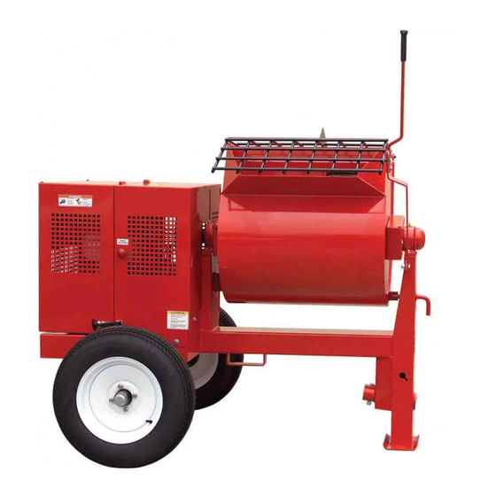
- Page 1 WM63SLF PLASTER AND MORTAR MIXER (MPOWER 177F-BH 9.0 HP GASOLINE ENGINE) Revision #0 (09/27/22) To find the latest revision of this publication or associated parts manual, visit our website at: www.multiquip.com THIS MANUAL MUST ACCOMPANY THE EQUIPMENT AT ALL TIMES.
-
Page 2: Proposition 65 Warning
PROPOSITION 65 WARNING PAGE 2 — WM63SLF-MIXER • OPERATION MANUAL — REV. #0 (09/27/22) -
Page 3: Silicosis/Respiratory Warnings
SILICOSIS/RESPIRATORY WARNINGS WARNING WARNING SILICOSIS WARNING RESPIRATORY HAZARDS Grinding/cutting/drilling of masonry, concrete, metal and Grinding/cutting/drilling of masonry, concrete, metal and other materials with silica in their composition may give other materials can generate dust, mists and fumes off dust or mists containing crystalline silica. Silica is a containing chemicals known to cause serious or fatal basic component of sand, quartz, brick clay, granite and injury or illness, such as respiratory disease, cancer,... -
Page 4: Table Of Contents
TABLE OF CONTENTS WM63SLF Plaster and Mortar Mixer Proposition 65 Warning ........... 2 Silicosis/Respiratory Warnings ........ 3 Safety Information ..........5-9 Safety Chain Connection ........10 Specifications (Mixer/Engine) ........ 11 Dimensions ............12 General Information ..........13 Components (Mixer) ......... 14-15 Components (Engine) .......... -
Page 5: Safety Information
SAFETY INFORMATION Do not operate or service the equipment before reading Potential hazards associated with the operation of this the entire manual. Safety precautions should be followed equipment will be referenced with hazard symbols which at all times when operating this equipment. may appear throughout this manual in conjunction with Failure to read and understand the safety safety messages. - Page 6 „ NEVER use accessories or attachments that are not „ Avoid wearing jewelry or loose-fi tting clothes that may recommended by Multiquip for this equipment. Damage snag on the controls or moving parts as this can cause to the equipment and/or injury to the user may result.
- Page 7 SAFETY INFORMATION ENGINE SAFETY WARNING „ NEVER place your hands inside the drum DANGER while starting or operating this equipment. „ Engine fuel exhaust gases contain poisonous carbon „ NEVER disconnect any emergency monoxide. This gas is colorless and odorless, and can or safety devices.
- Page 8 SAFETY INFORMATION FUEL SAFETY „ ALWAYS tie down equipment during transport by securing the equipment with rope. DANGER „ NEVER tip the engine to extreme angles during lifting „ DO NOT start the engine near spilled fuel or combustible as this may cause oil to gravitate into the cylinder head, fl uids.
- Page 9 SAFETY INFORMATION ENVIRONMENTAL SAFETY/DECOMMISSIONING EMISSIONS INFORMATION NOTICE NOTICE Decommissioning is a controlled process used to safely The gasoline engine used in this equipment has been retire a piece of equipment that is no longer serviceable. designed to reduce harmful levels of carbon monoxide If the equipment poses an unacceptable and unrepairable (CO), hydrocarbons (HC) and nitrogen oxides (NOx) safety risk due to wear or damage or is no longer cost...
-
Page 10: Safety Chain Connection
SAFETY CHAIN CONNECTION TOW BAR TO MIXER CONNECTION 2. Route the safety chain through the holes just above the tow bar, located on each side of the mixer stand. Reference Figure 1 for the installation of the safety chain. Loop the chain together and place under the tow bar. 1. -
Page 11: Specifications (Mixer/Engine)
SPECIFICATIONS (MIXER/ENGINE) Table 1. Mixer Specifications Capacity 6.3 cu. ft (178 liters) Bag Capacity 1-1/2 to 2-1/2 bags Weight 574 lbs. (260 kg.) Height W/Dump Handle 73 in. (185 cm.) Discharge Height 17.5 in. (44.4 cm.) Drive V-Belt/Gear Dump Action Manual Table 2. -
Page 12: Dimensions
DIMENSIONS Table 3. Dimensions Description Dimensions in. (cm) Length (w/Tow Bar) 67 in. (170 cm) Width 50 in. (127 cm) Height 56 in. (142 cm) OPTIONAL TOW BARS APPROXIMATE LENGTH HPC-1 36 IN. (91.44 CM) 1-INCH PIN COUPLER HBC-1 2-INCH BALL COUPLER HLC-1 LOOP COUPLER... -
Page 13: General Information
GENERAL INFORMATION APPLICATION ENGINE MAINTENANCE The MQ Whiteman WM63SLF mixer (drum capacity of 6.3 For basic engine maintenance, refer to the engine cu. ft./178 liters) is shipped completely assembled and has maintenance section in this manual. For a more detailed been factory tested and is ready for use. -
Page 14: Components (Mixer)
COMPONENTS (MIXER) Figure 5. Mixer Components PAGE 14 — WM63SLF-MIXER • OPERATION MANUAL — REV. #0 (09/27/22) - Page 15 COMPONENTS (MIXER) Figure 5 illustrates the basic components and controls of 12. Pivot Point/Zerk Fitting — There is a zerk grease the WM63SLF mixer. fitting on each end of the mixing drum. These fittings lubricate the dumping mechanism. Lubricate both 1.
-
Page 16: Components (Engine)
COMPONENTS (ENGINE) 3. Engine ON/OFF Switch — ON position permits engine starting, OFF position stops engine operations. 4. Recoil Starter (pull rope) — Manual-starting method. Pull the starter grip until resistance is felt, then pull briskly and smoothly. 5. Fuel Valve Lever — OPEN to let fuel flow, CLOSE to stop the flow of fuel. -
Page 17: Inspection
INSPECTION BEFORE STARTING 5. I NOTICE 1. Read all safety instructions at the beginning of manual. Reference engine manufacturer’s manual for specific servicing instructions. 2. Clean the unit, removing dirt and dust, particularly the engine cooling air inlet, carburetor and air cleaner. 3. - Page 18 INSPECTION V-BELT CHECK Check for worn or defective paddle blades (Figure 11). Make sure that all blades are adjusted properly. See blade Visually examine the V-belt (Figure 9) and determine if it adjustment procedure (Figure 13) in this manual. Replace is full of tiny cracks, frayed, has pieces of rubber missing, all defective or damaged blades immediately.
- Page 19 INSPECTION PADDLE BLADE ADJUSTMENT Adjust paddles as shown in Figure 13. TOW END CENTER TOW END CAST PADDLE CAST PADDLE DRUM END ENGINE END CAST PADDLE PADDLE BLADE IS TOO TIGHT AGAINST DRUM SIDE WALLS. CENTER ENGINE DRUM SIDE END CAST PADDLE INCORRECT INCORRECT INCORRECT...
-
Page 20: Operation
OPERATION This section is intended to assist the operator with the initial 3. Move the throttle lever (Figure 16) away from the slow start-up of the unit. It is extremely important that position, about 1/3 of the way toward the fast position. this section be read carefully before attempting to use the mixer in the field. - Page 21 OPERATION 6. Place the belt slip lever (Figure 19) in the START/STOP DRUM LATCH (disengaged) position. START/STOP STOP POSITION BLOCK TOW OR LOCKED POSITION Figure 21. Drum Lock Pin (Right Position) BELT SLIP LEVER 7. Pull the starter grip (Figure 22) lightly until you feel resistance, then pull briskly.
- Page 22 OPERATION MIXING/DUMPING STAND CLEAR OF DUMP HANDLE. HANDLE KICK-BACK IS POSSIBLE. 1. The paddle shaft inside the drum should be rotating at this time. 2. Add a small amount water to the mixing drum. 3. Lift the mixing bag compound onto the steel safety grate over the bag cutter and let the contents fall into the drum.
-
Page 23: Maintenance (Engine)
MAINTENANCE (ENGINE) Use Table 6 as a general maintenance guideline when servicing your engine. For more detail engine maintenance information, refer to the engine owner’s manual supplied with your engine. Table 6. Engine Maintenance Schedule EVERY FIRST EVERY 3 EVERY 6 EVERY 2 DESCRIPTION YEAR... - Page 24 MAINTENANCE (ENGINE) MAINTENANCE SPARK PLUG Perform scheduled maintenance procedures as defined in Remove and clean the spark plug (Figure 27). Adjust the Table 6 and below: spark plug gap to 0.027–0.031 in. (0.7–0.8 mm). This unit has electronic ignition, which requires no adjustments. DAILY Thoroughly remove dirt and oil from the engine and control area.
- Page 25 MAINTENANCE (ENGINE) ENGINE AIR CLEANER SPARK ARRESTER CLEANING 1. Remove the air cleaner cover and foam filter element Clean the spark arrester every 6 months or 100 hours of as shown in Figure 29. operation. 1. Remove the three 4 mm screws securing the exhaust BLOW COMPRESSED deflector (Figure 30) to the muffler protector, then AIR FROM THE...
- Page 26 MAINTENANCE (MIXER) DRUM HEAD SEALS There is 1 set of drum head seals (Figure 32) that will DRUM BEARING require lubrication. Lubricate the grease fitting for each BRACKET drum seal every 40 hours of operation using any grade lithium base grease. Apply grease until visible inside of mixing drum (over grease).
- Page 27 MAINTENANCE (MIXER) MAIN GEAR AND DRIVE PINION ALIGNMENT 1. Disconnect the spark plug wire (gasoline engines). If GREASE FITTING mixer is equipped with an electric motor remove power AND CAP cord from AC power receptacle. In addition make sure the clutch engagement lever is disengaged to relieve V-belt tension.
- Page 28 MAINTENANCE (MIXER) 4. If gear teeth are not contacting properly (Figure 37), Table 7 (Tire Wear Troubleshooting) will help pinpoint the causes and solutions of tire wear problems. adjust pillow block to correct the problem. Table 7. Tire Wear Troubleshooting Wear Pattern Cause Solution...
- Page 29 MAINTENANCE (MIXER) SUSPENSION NOTICE The rigid type axle and associated hardware (Figure 39) NEVER use an pneumatic air gun to tighten wheel should be periodically inspected for signs of excessive lug nuts. wear, elongation of bolt holes, and loosening of fasteners. 3.
-
Page 30: Maintenance (Mixer)
MAINTENANCE (MIXER) LONG-TERM STORAGE For storage of the mixer for over 30 days, the following is recommended: „ Drain the fuel tank completely, or add STA-BIL to the ® fuel. „ Run the engine until the gasoline in the carburetor is completely consumed. -
Page 31: Troubleshooting (Engine)
TROUBLESHOOTING (ENGINE) Troubleshooting (Engine) Symptom Possible Problem Solution Spark plug bridging? Check gap, insulation or replace spark plug. Carbon deposit on spark plug? Clean or replace spark plug. Short circuit due to defi cient spark plug Check spark plug insulation, replace if worn. insulation? Improper spark plug gap? Set to proper gap. - Page 32 TROUBLESHOOTING (ENGINE) Troubleshooting (Engine) - continued Symptom Possible Problem Solution Air cleaner dirty? Clean or replace air cleaner. Improper level in carburetor? Check fl oat adjustment, rebuild carburetor. Weak in power, compression is proper and does not misfi re. Defective spark plug? Clean or replace spark plug.
-
Page 33: Troubleshooting (Mixer)
TROUBLESHOOTING (MIXER) Mixer Troubleshooting Worn or defective V-belt? Replace V-belt. Blades will not rotate. Check position of adjustment lever. Adjustment lever mis-aligned? Adjust if necessary. Material leaking from drum ends. Worn or defective paddle shaft seals? Replace seals. Defective or worn drum support Apply grease to bracket or replace. - Page 34 © COPYRIGHT 2022, MULTIQUIP INC. Multiquip Inc , the MQ logo are registered trademarks of Multiquip Inc. and may not be used, reproduced, or altered without written permission. All other trademarks are the property of their respective owners and used with permission.
Need help?
Do you have a question about the WHITEMAN WM63SLF and is the answer not in the manual?
Questions and answers