Table of Contents
Advertisement
Quick Links
OperatiOn and parts Manual
series
MOdels
WM63H5, WM63H8
WM63e
plaster and MOrtar Mixer
(HOnda Gx160ut1Hx2/Gx240ut1Ha2
GasOline enGines)
Revision #0 (09/27/12)
To find the latest revision of this
publication, visit our website at:
www.multiquip.com
THIS MANUAL MUST ACCOMPANY THE EQUIPMENT AT ALL TIMES.
Advertisement
Table of Contents

Related Manuals for MULTIQUIP WM63H5


Summary of Contents for MULTIQUIP WM63H5
- Page 1 OperatiOn and parts Manual series MOdels WM63H5, WM63H8 WM63e plaster and MOrtar Mixer (HOnda Gx160ut1Hx2/Gx240ut1Ha2 GasOline enGines) Revision #0 (09/27/12) To find the latest revision of this publication, visit our website at: www.multiquip.com THIS MANUAL MUST ACCOMPANY THE EQUIPMENT AT ALL TIMES.
-
Page 2: Proposition 65 Warning
prOpOsitiOn 65 WarninG Engine exhaust some its constituents, and some dust created by power sanding, sawing, grinding, drillingandotherconstructionactivities contains chemicals known to the State of California to cause cancer, birth defects and other reproductive harm. Some examples of these chemicals are: Leadfromlead-basedpaints. -
Page 3: Silicosis/Respiratory Warnings
silicOsis/respiratOry WarninGs WARNING WARNING SILICOSIS WARNING RESPIRATORY HAZARDS Grinding/cutting/drilling of masonry, concrete, metal and Grinding/cutting/drilling of masonry, concrete, metal and other materials with silica in their composition may give other materials can generate dust, mists and fumes off dust or mists containing crystalline silica. Silica is a containing chemicals known to cause serious or fatal basic component of sand, quartz, brick clay, granite and injury or illness, such as respiratory disease, cancer,... -
Page 4: Table Of Contents
Of cOntents WM63H5/WM63H8/WM63e component drawings plaster and Mortar Mixers Nameplate And Decals ........40-41 Frame Assembly ..........42-43 Proposition 65 Warning ........... 2 Paddle Shaft Assembly ........44-45 Silicosis/Respiratory Warnings ........ 3 Steel Tub Assembly .......... 46-47 Table Of Contents ............ 4 Drum And Paddle Shaft Complete Assembly ... -
Page 5: Parts Ordering Procedures
, 2006 order via internet (dealers only) Best deal! If you have an MQ Account, to obtain a Username Order parts on-line using Multiquip’s SmartEquip website! and Password, E-mail us at: parts@multiquip. com. I View Parts Diagrams I Order Parts To obtain an MQ Account, contact your District Sales Manager for more information. -
Page 6: Safety Information
safety infOrMatiOn Do not operate or service the equipment before reading Potential hazards associated with the operation of this the entire manual. Safety precautions should be followed equipment will be referenced with hazard symbols which at all times when operating this equipment. may appear throughout this manual in conjunction with Failure to read and understand the safety safety messages. - Page 7 „ never use accessories or attachments that are not „ Avoid wearing jewelry or loose fi tting clothes that may recommended by Multiquip for this equipment. Damage snag on the controls or moving parts as this can cause to the equipment and/or injury to user may result.
- Page 8 safety infOrMatiOn mixer saFeTY engine saFeTY (gasoline models onlY) danger danger „ never operate the equipment in an explosive „ Engine fuel exhaust gases contain poisonous carbon monoxide. This gas is colorless and odorless, and can atmosphere or near combustible materials. An explosion or fi re could result causing severe cause death if inhaled.
- Page 9 safety infOrMatiOn Fuel saFeTY (gasoline models onlY) power Cord/Cable safety danger danger „ do noT start the engine near spilled fuel or combustible „ never let power cords or cables lay in water. fl uids. Fuel is extremely fl ammable and its vapors can „...
- Page 10 safety infOrMatiOn Towing saFeTY environmenTal saFeTY CauTion NOTICE „ Check with your local county or state safety towing „ Dispose of hazardous waste properly. regulations, in addition to meeting Department of Examples of potentially hazardous waste Transportation (DOT) Safety Towing Regulations, are used motor oil, fuel and fuel fi lters.
-
Page 11: Safety Chain Connection
safety cHain cOnnectiOn 2. Route the safety chain through the holes just above CauTion the tow bar, located on each side of the mixer stand. never tow the mixer with the safety chain removed. Loop the chain together and place under the tow bar. The safety chain is intended to prevent complete Secure the loop with the connector link. -
Page 12: Specifications
specificatiOns Table 1. mixer specifications Capacity 6.3 cu. ft (178 liters) Bag Capacity 1-1/2 to 2-1/2 bags weight 574 lbs. (260 kg.) Height w/dump Handle 73 in. (185 cm.) discharge Height 17.5 in. (44.4 cm.) drive V-Belt/Gear dump action Manual Table 2. -
Page 13: Dimensions
diMensiOns Table 3. dimensions description dimensions in. (cm) Length (w/Tow Bar) 67 in. (170 cm) Width 50 in. (127 cm) Height 56 in. (142 cm) OPTIONAL TOW BARS APPROXIMATE LENGTH HPC-1 36 IN. (91.44 CM) 1-INCH PIN COUPLER HBC-1 2-INCH BALL COUPLER HLC-1 LOOP COUPLER... -
Page 14: General Information
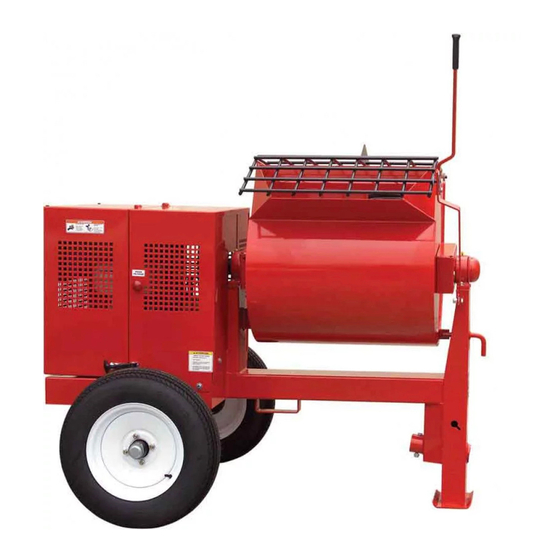
General infOrMatiOn appliCaTion Ensure that the extension cable is carefully laid out avoiding wet areas, sharp edges and locations where vehicles might The MQ Whiteman WM63 Series mixers (drum capacity run over it. Avoid allowing the extension cable to be trapped of 6.3 cu. -
Page 15: Components
cOMpOnents Figure 4 illustrates the basic components and controls of 9. safety grill — Provided for operator safety. This safety the WM63 Series mixer. grill is designed to keep hands and solid objects out of the mixing drum when in use. This grill should be closed at all times when mixer is in use. -
Page 16: Inspection
inspectiOn BeFore sTarTing 5. I NOTICE 1. Read all safety instructions at the beginning of manual. Reference engine manufacturer’s manual for specific servicing instructions. 2. Clean the unit, removing dirt and dust, particularly the engine cooling air inlet, carburetor and air cleaner. UPPER LIMIT 3. - Page 17 inspectiOn v-BelT CHeCk Check for worn or defective paddle blades (Figure 9). Make sure that all blades are adjusted properly. See blade Visually examine the V-belt (Figure 7) and determine if it adjustment procedure (Figure 13) in this manual. Replace is full of tiny cracks, frayed, has pieces of rubber missing, all defective or damaged blades immediately.
-
Page 18: Basic Engine
basic enGine 2. Throttle lever — Used to adjust engine RPM speed (lever advanced forward SLOW, lever back toward operator FAST). 3. engine on/oFF switch — ON position permits engine starting, OFF position stops engine operations. 4. recoil starter (pull rope) — Manual-starting method. Pull the starter grip until resistance is felt, then pull briskly and smoothly. -
Page 19: Electric Motor
electric MOtOr eleCTriC moTor Table 6. electric motor wiring information 115-230 vaC - single phase motor For maintenance care and operation of the electric motor, refer to your electric motor instruction booklet furnished Horsepower NEMA Mating NEMA with the motor. rating Plug Receptacle... - Page 20 electric MOtOr The electric motor supplied is wired for 115 VAC grounded operation. Make certain that the correct size grounded (3-wires) extension cord is used. See Table 7 below. Table 7. recommended extension Cord sizes 50 ft. 75 ft. 100 ft. 200 ft.
-
Page 21: Paddle Blade Adjustment
paddle blade adjustMent Adjust paddles as shown in Figure 13. TOW END CENTER TOW END CAST PADDLE CAST PADDLE DRUM END ENGINE END CAST PADDLE PADDLE BLADE IS TOO TIGHT AGAINST DRUM SIDE WALLS. DRUM SIDE CENTER ENGINE END CAST PADDLE INCORRECT INCORRECT INCORRECT... -
Page 22: Start-Up
start-up This section is intended to assist the operator with the initial 3. Move the throttle lever (Figure 16) away from the slow start-up of the unit. It is extremely important that position, about 1/3 of the way toward the fast position. this section be read carefully before attempting to use the mixer in the field. - Page 23 start-up 6. Place the belt slip lever (Figure 19) in the START/STOP DRUM LATCH (disengaged) position. START/STOP STOP POSITION BLOCK TOW OR LOCKED POSITION Figure 21. Drum Lock Pin (Right Position) BELT SLIP LEVER 7. Pull the starter grip (Figure 22) lightly until you feel resistance, then pull briskly.
-
Page 24: Operation
OperatiOn mixing/dumping STAND CLEAR OF DUMP HANDLE. HANDLE KICK-BACK IS POSSIBLE. 1. The paddle shaft inside the drum should be rotating at this time. 2. Add a small amount water to the mixing drum. 3. Lift the mixing bag compound onto the steel safety grate over the bag cutter and let the contents fall into the drum. - Page 25 nOtes wm63-series mixer • operaTion and parTs manual — rev. #0 (069/27/12) — page 25...
-
Page 26: Maintenance (Engine)
Maintenance (enGine) Use Table 8 as a general maintenance guideline when servicing your engine. For more detail engine maintenance information, refer to the engine owner’s manual supplied with your engine. Table 8. engine maintenance schedule everY FirsT everY 3 everY 6 everY 2 desCripTion Year... - Page 27 Maintenance (enGine) Perform the scheduled maintenance procedures as defined OIL FILLER CAP by Table 8 and below: DIPSTICK dailY „ Thoroughly remove dirt and oil from the engine and control area. Clean or replace the air cleaner elements as necessary. Check and retighten all fasteners as SEALING DRAIN WASHER...
-
Page 28: Maintenance (Mixer)
Maintenance (Mixer) drum Head seals There is 1 set of drum head seals (Figure 29) that will DRUM BEARING require lubrication. Lubricate the grease fitting for each BRACKET drum seal every 40 hours of operation using any grade lithium base grease. Apply grease until visible inside of mixing drum (over grease). - Page 29 Maintenance (Mixer) main gear and drive pinion alignmenT 1. Disconnect the spark plug wire (gasoline engines). If GREASE FITTING mixer is equipped with an electric motor remove power AND CAP cord from AC power receptacle. In addition make sure the clutch engagement lever is disengaged to relieve V-belt tension.
- Page 30 Maintenance (Mixer) 4. If gear teeth are not contacting properly (Figure 34), adjust pillow block to correct the problem. GREASE FITTING HEAL CONTACT FACE CONTACT PROPER CONTACT FLANK CONTACT CONTACT Figure 34. Gear Teeth Alignment gear luBriCaTion Figure 36. Grease Fittings Electric Motor The surface of the pinion and main gear (Figure 35) should be very lightly greased.
- Page 31 Maintenance (Mixer) 3. After first road use, retorque all lug nuts in sequence. Table 9. Tire wear Troubleshooting Check all wheel lug nuts periodically. Wear Pattern Cause Solution Adjust pressure to Center Over Infl ation particular load per Wear tire manufacturer Adjust pressure to Edge Under...
- Page 32 Maintenance (Mixer) suspension The rigid type axle and associated hardware (Figure 38) should be periodically inspected for signs of excessive wear, elongation of bolt holes, and loosening of fasteners. Replace all damaged parts immediately. SINGLE PHASE 115/230 VAC 2.0 HP ELECTRIC MOTOR Figure 39.
- Page 33 Maintenance (Mixer) mixer sTorage For storage of the mixer for over 30 days, the following is recommended: „ Drain the fuel tank completely, or add STA-BIL to the fuel. „ Run the engine until the fuel is completely consumed. „ Completely drain used oil from the engine crankcase and fill with fresh clean oil, then follow the procedures described in the engine manual for engine storage.
-
Page 34: Troubleshooting
trOublesHOOtinG Troubleshooting (engine) symptom possible problem solution Spark plug bridging? Check gap, insulation or replace spark plug. Carbon deposit on spark plug? Clean or replace spark plug. Short circuit due to defi cient spark plug Check spark plug insulation, replace if worn. insulation? Improper spark plug gap? Set to proper gap. - Page 35 trOublesHOOtinG Troubleshooting (engine) - continued symptom possible problem solution Air cleaner dirty? Clean or replace air cleaner. Improper level in carburetor? Check fl oat adjustment, rebuild carburetor. Weak in power, compression is proper and does not misfi re. Defective spark plug? Clean or replace spark plug.
- Page 36 trOublesHOOtinG mixer Troubleshooting Worn or defective V-belt? Replace V-belt. Blades will not rotate. Check position of adjustment lever. Adjustment lever mis-aligned? Adjust if necessary. Material leaking from drum ends. Worn or defective paddle shaft seals? Replace seals. Defective or worn drum support Apply grease to bracket or replace.
-
Page 37: Wiring Diagram
WirinG diaGraM wm63-series mixer • operaTion and parTs manual — rev. #0 (069/27/12) — page 37... -
Page 38: Explanation Of Code In Remarks Column
A blank entry generally indicates that the item is not sold assembly/kit that can be purchased, or is not available separately or is not sold by Multiquip. Other entries will for sale through Multiquip. be clarifi ed in the “Remarks” Column. -
Page 39: Suggested Spare Parts
suGGested spare parts wm63-series plasTer and morTar mixer wiTH Honda gx160uT1Hx2/gx240uT1Ha2 engines and 1.5 Hp eleCTriC moTor. 1 to 3 units Qty. description 6....491107 ....V-BELT A32, HONDA ENGINE (GX160, 5.5 HP) 6....07055-034 ....V-BELT 4L340, HONDA ENGINE (GX240, 8.0 HP) 6....491112 ....V-BELT A40, ELECTRIC MOTOR 2....EM914288 ....OIL SEAL, AXLE 4....EM903113 ....BEARING, CONE, AXLE 4....EM903012 ....BEARING, CUP, AXLE... -
Page 40: Nameplate And Decals
naMeplate and decals SAFETY INSTRUCTIONS 1. Read owner’s manual before operating. 2. Keep unauthorized and untrained people away from machine during operation. 3. Make sure all safety devices are in place before this machine is started. 4. Make sure engine is turned off and spark plug wire is disconnected before cleaning the machine. - Page 41 naMeplate and decals parT no. parT name QTY. remarks EM948630 DECAL, PUSH TO STOP 521228 DECAL, DO NOT SMOKE 521229 DECAL, READ MANUAL, CRUSH HAZARD 515275 DECAL, MQ WHITEMAN LOGO SMALL 504714 DECAL, MQ WHITEMAN LOGO LARGE 520935 DECAL, SAFETY INSTRUCTIONS 521230 DECAL, HANDLE KICK BACK, SAFETY GRATE, CRUSH HAZARD...
-
Page 42: Frame Assembly
fraMe assy. MOUNT PILLOW BLOCKS MOUNT DRUM FOR PINION SHAFT HERE BEARING HERE MOUNT DRUM BEARING HERE CHAIN & LINK OPTIONAL TOW BARS page 42 — wm63-series mixer • operaTion and parTs manual — rev. #0 (09/27/12) - Page 43 fraMe assy. parT no. parT name QTY. remarks 514842 LOCK, PIN 491692 COTTER PIN 530023 SPRING LOCKING PIN 507444 WASHER, FLAT 3/4" 514834 MAIN FRAME 530013 CLUTCH HANDLE LEVER 20278-001 CLUTCH HANDLE GRIP EM963692 BOLT 1/2" UNC 1-1/2" 492584 NUT, LOCK 1/2" 514802 AXLE, UNIVERSAL 10176...
- Page 44 paddle sHaft assy. page 44 — wm63-series mixer • operaTion and parTs manual — rev. #0 (09/27/12)
-
Page 45: Paddle Shaft Assembly
paddle sHaft assy. parT no. parT name QTY. remarks 514752 PADDLE SHAFT 492584 NUT, LOCK 1/2" 530140C PADDLE ARM, CENTER ENGINE END 3215 SCREW, HHC 1/2-13 X 3-1/2 EM200292 INSERT, PADDLE ARM 530141 PADDLE ARM, ENGINE END 6109170 WASHER, FLAT 1/2" EM200297 U-BOLT, END PADDLES 530143... -
Page 46: Steel Tub Assembly
steel tub assy. PART OF REAR FRAME PART OF FRONT FRAME NOTES: SET SCREWS AND BEARING COLLAR ARE INCLUDED WITH BEARING AND CANNOT BE PURCHASED SEPARATELY. page 46 — wm63-series mixer • operaTion and parTs manual — rev. #0 (09/27/12) - Page 47 steel tub assy. parT no. parT name QTY. remarks 530028 DRUM BEARING BRACKET 3249 CAP, DUST 20561-001 BEARING SEALED ..........2....SET SCREWS AND BEARING .....................COLLAR CANNOT BE SOLD .....................SEPARATELY. 491008 CAP, GREASE FITTING EM916019 FITTING, GREASE EM969013 NUT, NYLOCK 3/8" 3019092 WASHER, FLAT 3/8"...
-
Page 48: Drum And Paddle Shaft Complete Assembly
druM and paddle sHaft cOMplete assy. page 48 — wm63-series mixer • operaTion and parTs manual — rev. #0 (09/27/12) - Page 49 druM and paddle sHaft cOMplete assy. parT no. parT name QTY. remarks 516069 DRUM AND SHAFT COMPLETE ASSY....1..INCLUDES ITEMS LISTED BELOW 530028 DRUM BEARING BRACKET 3249 CAP, DUST 20561-001 BEARING SEALED 491008 CAP, GREASE FITTING EM916019 FITTING, GREASE EM969013 NUT, LOCK 3/8"...
-
Page 50: Axle Assembly
axle assy. page 50 — wm63-series mixer • operaTion and parTs manual — rev. #0 (09/27/12) - Page 51 axle assy. parT no. parT name QTY. remarks 3469 DUST CAP 29194 LUG NUTS 516476 TIRE AND RIM, TOWMASTER II 8164 CASTLE NUT 1-20 JAM EM924008 COTTER PIN 1/8" X 1-1/2' EM511159 WASHER, FLAT, .087" THICKNESS EM501299 WASHER, FLAT, .135" THICKNESS EM903113 BEARING CONE EM903012...
-
Page 52: Engine Assembly
enGine assy. page 52 — wm63-series mixer • operaTion and parTs manual — rev. #0 (09/27/12) - Page 53 enGine assy. parT no. parT name QTY. remarks EM969013 NUT NYLOK 3/8" NC G5 3019092 FLAT WASHER 3/8 EM905016 PILLOW BLOCK BEARING 492378 BOLT 3/8" NC X 1-3/4" G5 JISB2804C25 RING, RETAINING 513868 PINION GEAR 500214 KEY, SQUARE 1/4 X 1/4 X 1-1/2 502226 PINION SHAFT 492077...
- Page 54 electric MOtOr assy. page 54 — wm63-series mixer • operaTion and parTs manual — rev. #0 (09/27/12)
-
Page 55: Electric Motor Assembly
electric MOtOr assy. parT no. parT name QTY. remarks EM969013 NUT NYLOK 3/8" G5 3019092 FLAT WASHER 3/8 EM905016 PILLOW BLOCK BEARING 492378 BOLT 3/8 X 1-3/4" G5 20216-001 PINION SHAFT 20061-001 PULLEY (LARGE) 500214 KEY, 1/4 X 1/4 X 1-1/2 492467 SET SCREW, 5/16' NC 3/8"... -
Page 56: Cabinet Assembly
cabinet assy. 12 OZ. SPRAY PAINT NOTES: COMPLETE LATCH ASSEMBLY INCLUDES ITEMS WITHIN DASHED LINES. ITEMS CANNOT BE PURCHASED SEPARATELY. page 56 — wm63-series mixer • operaTion and parTs manual — rev. #0 (09/27/12) - Page 57 cabinet assy. parT no. parT name QTY. remarks 515014 CABINET, ENGINE W/DECALS ......1....INCLUDES ITEMS W/$ 490202 RUBBER PROTECTOR 13287 LOCK NUT 8-32 2203 WASHER, FLAT #10 1307 SCREW PHP 8-32 X 1/2" 491010 LATCH ASSY., COMPLETE EM963610 CAP SCREW 3/8" NC X 1-1/4 G8 3019092 WASHER, FLAT 3/8"...
-
Page 58: Terms And Conditions Of Sale - Parts
Multiquip be $5.00. meeting this requirement. liable for loss of profi t or good will or for any Special order items. - Page 59 nOtes wm63-series mixer • operaTion and parTs manual — rev. #0 (069/27/12) — page 59...
- Page 60 © COPYRIGHT 2012, MULTIQUIP INC. Multiquip Inc, the MQ logo and the Whiteman logo are registered trademarks of Multiquip Inc. and may not be used, reproduced, or altered without written permission. All other trademarks are the property of their respective owners and used with permission.
Need help?
Do you have a question about the WM63H5 and is the answer not in the manual?
Questions and answers