WEIGL ProCommander Series Wiring Diagram
Hide thumbs
Also See for ProCommander Series:
- Menu plan (9 pages) ,
- Instruction manual (102 pages) ,
- Wiring diagrams (12 pages)
Advertisement
Quick Links
Advertisement

Related Manuals for WEIGL ProCommander Series


Summary of Contents for WEIGL ProCommander Series
- Page 1 Wiring Diagram...
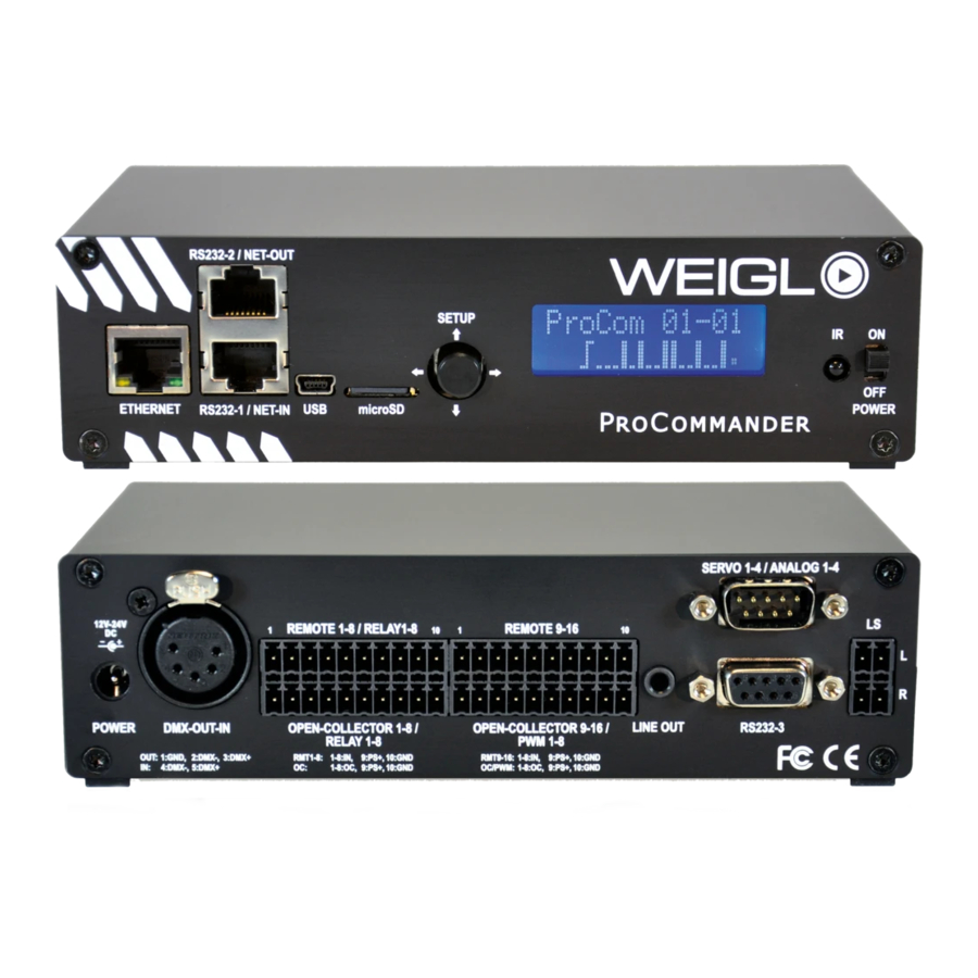
- Page 2 8: GND (!ssi1#) RS232-1 shares RS485-1 RS232-2 shares RS485-2 Daisy-Chain Connection for Pro-I/O NETWORK Press button to store USB for Control and Configuration permanently changes in menu Instruction Manual Volume + - www.Weigl.Support NGLISH Volume - Handbuch - www.WeiglControl.com/de/handbuch EUTSCH...
- Page 3 EXTERNAL POWER SUPPLY REAR WIRING DIAGRAM FOR ProCommander ® INPUT CIRCUIT IN9-IN16 IN9-IN16 ANALOG OUT 1, max. 10mA 0-10V TO _AD-CONVE RT ER ANALOG OUT 2, max. 10mA INPUT CIRCUIT IN1-IN8 max. 24V DC 0-10V IN1-IN8 ANALOG IN 1 ANALOG IN 8 (0-10V) (0-10V) ANALOG OUT 3, max.
-
Page 4: Relay Option
EXTERNAL POWER SUPPLY REAR WIRING DIAGRAM FOR ProCommander ® and ProCommander ® PHX 2 RELAY OPTION INPUT CIRCUIT IN9-IN16 IN9-IN16 ANALOG OUT 1, max. 10mA 0-10V TO _AD-CONVE RT ER ANALOG OUT 2, max. 10mA max. 24V DC 0-10V ANALOG IN 1 ANALOG IN 8 (0-10V) (0-10V) - Page 5 EXTERNAL POWER SUPPLY REAR WIRING DIAGRAM FOR ProCommander ® and ProCommander ® PHX 2 POSITIVE OPTION INPUT CIRCUIT IN9-IN16 IN9-IN16 ANALOG OUT 1, max. 10mA 0-10V TO _AD-CONVE RT ER ANALOG OUT 2, max. 10mA max. 24V DC INPUT CIRCUIT IN1-IN8 0-10V IN1-IN8 ANALOG IN 1...
- Page 6 REAR WIRING DIAGRAM FOR ProCommander ® PHX 2 INPUT CIRCUIT IN9-IN16 IN9-IN16 TO _AD-CONVE RT ER INPUT CIRCUIT IN1-IN8 max. 24V DC IN1-IN8 ANALOG IN ANALOG IN 1 (0-10V) 8 (0-10V) EXTERNAL AMPLIFIER TO _IN 1-8 max. 24V DC DMX512-IN 4x INTERNAL 20W AMPLIFIER LEFT 4/8 Ohm...
- Page 7 INPUT CI RCUIT IN1-IN8 REAR WIRING DIAGRAM FOR ProCommander ® IN 1-IN 8 16 Key Matrix Connection TO _IN1-8 Firmware version >= 1.25 required! max. 24V DC Matrix Wiring Parallel Wiring Activate matrix function: !skm1# Deactivate matrix function: !skm0# Will be stored in EEProm, therefore function is the same after power cycle.
- Page 8 REAR WIRING DIAGRAM FOR ProCommander ® LX 2 INPUT CIRCUIT IN9-IN16 ANALOG OUT 1, max. 10mA IN 9-IN 16 0–10 V TO _AD-CONVE RT ER ANALOG OUT 2, max. 10mA INPUT CI RCUIT IN1-IN8 max. 24V DC 0–10 V IN 1-IN 8 ANALOG IN 1 ANALOG IN 8 (0-10V)
- Page 9 REAR WIRING DIAGRAM FOR ProCommander LX 2 ® RELAY OPTION INPUT CIRCUIT IN9-IN16 ANALOG OUT 1, max. 10mA IN 9-IN 16 0–10 V TO _AD-CONVE RT ER ANALOG OUT 2, max. 10mA INPUT CI RCUIT IN1-IN8 IN 1-IN 8 max. 24V DC 0–10 V ANALOG IN 1 ANALOG IN 8...
- Page 10 REAR WIRING DIAGRAM FOR ProCommander LX 2 ® POSITIVE OPTION INPUT CIRCUIT IN9-IN16 ANALOG OUT 1, max. 10mA IN 9-IN 16 0–10 V TO _AD-CONVE RT ER ANALOG OUT 2, max. 10mA INPUT CI RCUIT IN1-IN8 max. 24V DC 0–10 V IN 1-IN 8 ANALOG IN 1 ANALOG IN 8...
- Page 11 REAR WIRING DIAGRAM FOR ProCommander ® EXTERNAL POWER SUPPLY + Pin 5.1 and Pin 5.2 internally connec ted! LOAD 1 LOAD 4 Pin 6.1 and Pin 6.2 internally connec ted! EXTERNAL POWER SUPPLY GND INPUT CI RCUIT IN1-IN8 IN 1-IN 8 RS232 TO _IN1-8 Audio Out RIGHT -...
- Page 12 Weigl Support and Solutions Center | www.Weigl.Support WeiglControl Americas +14409415849 © 2007 - 2018 - Weigl GmbH & Co KG and WeiglControls ProCommander is registered U.S. trademark #5,260,804 ® Information deemed accurate, but not guaranteed. Subject to change without notice.
Need help?
Do you have a question about the ProCommander Series and is the answer not in the manual?
Questions and answers