Table of Contents
Advertisement
Quick Links
EN
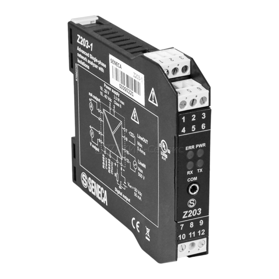
Z203-1
General Description
Model Z203-1 is a complete single-phase network analyser suited for use with up to 500
Vac voltage range and 5 A (35 to 75 Hz) current.
The instrument provides all the following electrical measurable quantities
Watt Var Frequency, Energy, Cos
,
,
Measurements are read through serial communication and both floating point and
normalised format (except for energy). The DIP-switches (or Modbus registers) can be set
for the analogue retransmission of any Vrms, Irms, Watt, Var, Frequency, and Cos
quantity. The module is also distinguished by:
Facilitated power supply and serial bus wiring by means of the bus housed in the DIN rail.
Communication configurability through DIP-switch or software.
R
s485 serial communication with MODBUS-RTU protocol, maximum 32 nodes.
Power input isolation: 3750 Vac respect to all the other circuits.
Isolation between communication and power supply: 1500 Vac.
Isolation between retransmitted output and power supply: 1500 Vac.
Analogue output signal settable in voltage or current.
Possibility for connection and management by an external CT (only if Z203-1 is configurated
by a configuration software).
Energy counter: pulse digital output, reading on Modbus register (the count is saved into
retentive memory).
Easy configuration with the software Easy, downloadable from www.seneca.it
Technical Specifications
Power Supply:
Consumption:
Communication Ports:
Protocol:
Installation category:
Input/Retransmitted output
Voltage Input :
Current Input :
Class/Base Precision :
Analog Output
Output Voltage :
Output Current :
Transmission error :
Advanced Single-phase Network Analyser
.
10 – 40 V o 19 – 28 V (50 – 60 Hz)
max 2.5 W
-RS485, 1200..115200 Baud.
-RS232, 2400 Baud, Address: 01, Parity: NO, Data: 8
bits; Stop bits: 1.
MODBUS-RTU
II (Up to 300 V)
up to 500 Vac; frequency: 35 to 75 Hz.
Current input rated range: 5 Arms, Max peak factor: 3,
Max Current : 15 A, Frequency: 35 to 75 Hz.
Voltmeter : 0,5 %.
Amperometer : 0,5 %.
Wattmeter : 0,5 %. (active power)
0..10 Vdc, 0..5 Vdc, minimum load resistance: 2 k .
0..20 mA, 4..20 mA, maximum load resistance: 500
0,1 % (max. range).
MI00117 -E
8
: Vrms Irms
,
ENGLISH - 1/16
,
Advertisement
Table of Contents

Related Manuals for Seneca Z203-1


Summary of Contents for Seneca Z203-1
- Page 1 Advanced Single-phase Network Analyser General Description Model Z203-1 is a complete single-phase network analyser suited for use with up to 500 Vac voltage range and 5 A (35 to 75 Hz) current. The instrument provides all the following electrical measurable quantities...
- Page 2 Digital Output for pulses (energy counter) Type : Passive (it must be powered), R > 480 Range : 50 mA Insulation : 1500 Vpeak Screw terminal : 1 and 6 (common with GND analogue output) Insulation voltage : 3750 Vac between the measurement input and all the other circuits.1500 Vac between power supply and communication.
-
Page 3: Installation Rules
RS485 SERIAL PORT AND POWER SUPPLY The electric connections for power supply can be made by using either the terminals or the bus for the Seneca DIN rail. The RS485 bus connections are available only by using the bus for the DIN rail. -
Page 4: Power Supply
The module accepts an input voltage of up to a maximum 500 Vac. The input voltage is connected to Terminals 10 and 12, whereas the load to be analysed is connected to Terminals 7 and 9. Z203-1 LINE OUT LINE IN... -
Page 5: Analogue Output
The module has a digital output: each pulse (200 ms) corresponds to a given number of increments of the energy counted (see the register Digital Output Ratio). Imax=V/R=50mA Digital output EXAMPLE OF CONNECTION WITH AN EXTERNAL CT (in this case, configure the Z203-1 using software, NOT dip-switch) P1/K P2/L S1/K S2/L... - Page 6 Steady ON Data are being transmitted through the RS485 communication port Serial interface For detailed information on RS485 serial interface, consult the documentation provided by the website www.seneca.it, in the section Prodotti/Serie Z-PC/MODBUS TUTORIAL DIP-SWITCH SETTING Default configuration The instrument leaves the factory with all DIP-switches configured in position 0. The settings of the DIP-switches defines the module's communication parameters: address and speed.
-
Page 7: Output Type
Terminator ON, the SW3-2 is not used. Programming For the product's programming and/or configuration tools, consult the website www.seneca.it. During initial programming, the EEPROM (SW3 ..8 in OFF position) default setting values originally programmed as follows can be used: Address = 01 SPEED =38400 Baud PARITY= none BIT NUMBER = 8 STOP BIT=1. -
Page 8: Overall Dimensions
Dip-switch and Modbus register Frontal Panel and Led If all the dip-switch of SW2 are equal to zero, so “00000000”: the module acquires the configuration from 1 2 3 EEPROM for: nominal frequency, output-type, output- 4 5 6 electric value, retransmitted output, electric start scale, electric end scale (see the modbus registers). -
Page 9: Modbus Registers
MODBUS REGISTERS Z203-1 has MODBUS 16 bits (words) registers, accessible by RS485 or RS232 serial communication. In the next paragraphs, we shall describe the supported MODBUS commands, and the functions of the registers. Supported MODBUS Commands Code Function Description Read Holding Registers Reading of registers up to 16 words at a time within the same group . - Page 10 GROUP 1 REGISTER Description ADD. Bit [15:8]: contain the module's ID MACHINE ID 40001 Bit [7:0] contain the firmware's external revision. ADDR Register for the setting of the module's 40002 address and parity control. Set the module's address. Permissible values Bit [15:8] from 0x00...
- Page 11 FREQUENCY Register to set the network frequency 40007 Bit [15:0] If the dip switch Sw2 are configurated as «00000000»: 0=50 Hz; 1=60 Hz OUT TYPE Register to set the range of the analogue 40008 output If SW2 are equal to “00000000”, analogue output Bit [15:0] is: 0=voltage;...
- Page 12 WATT_FLOAT_M Active power measurement in floating point 40085 (most significant word . ) Active power measurement in W (MSW). Bit [15:0] WATT_FLOAT_L Active power measurement in floating point 40086 (least significant word . ) Active power measurement in W (LSW). Bit [15:0] FREQ_FLOAT_M Frequency measurement in floating point...
- Page 13 GROUP 3 STATUS Status Register 40093 Bit 7 Zero cross error 1: signals that the input voltage is less than 40 Bit [6:5] Reserved. Bit 4 Communication error with the sensor: 1: signals an error of communication with the sensor. Bit [3:1] Reserved.
- Page 14 COMMAND Register of command 40102 0xB A C A: this command loads the value Bit [15:0] CommandAux in the register energy; 0x6500 forces the RESET of the module. COMMANDAUX_M Register of auxi li ary command (most 40103 significant word) Value to load in the register energy Bit [15:0] COMMANDAUX_L Regi ster of auxil iary comm and (least...
- Page 15 STOP SCALE Stop scale of analogue output in floating-point 40116 OUTPUT_M (most significant word) Output stop scale value. To know the analogue Bit [15:0] output, see reg.40008 (if SW2 are equal to “00000000”) STOP SCALE Stop scale of analogue output in floating-point 40117 OUTPUT_L (least significant word)
-
Page 16: Appendix A : Retransmission Scaling (From Dip-Switch) 100 % Scaling: Retransmission Scaling
This document is property of SENECA srl. Duplication and reprodution are forbidden, if not authorized. Contents of the present documentation refers to products and technologies described in it. All technical data contained in the document may be modified without prior notice Content of this documentation is subject to periodical revision.
Need help?
Do you have a question about the Z203-1 and is the answer not in the manual?
Questions and answers