Table of Contents
Advertisement
Quick Links
EN
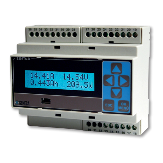
S203TA Advanced Three-phase Network Analyzer
General Description
Model S203TA is a complete three-phase network analyzer suited for u s e w i t h u p t o
600Vac voltage range, and current range given by the nominal range of the CTs with 5A
Output connected.
The instrument provides all the following electrical measurable quantities: Vrms, Irms,
Watt, Var, Va, Frequency, Cos
(except frequency) are available both single-phase and three-phase.
Measurements are read through serial communication both in floating point and
normalised format (except Frequency and Active Energy).
The DIP-switches can be set for the analog retransmission of any Vrms, Irms, Watt and
Cos quantity either single phase or three-phase, or any phase chosen (by specific
MODBUS registry). The module is also distinguished by:
Communication configurability through DIP-switch or software.
RS485 serial communication with MODBUS-RTU protocol, maximum 32 nodes.
Easy-wiring of power supply and serial bus by means of the bus housed in the DIN rail.
High precision: 0,2 % class.
Protection against ESD discharge up to 4 kV.
Power input insulation: 3750 Vac towards all the other circuits.
Insulation between communication and power supply: 1500Vac.
Insulation between retransmitted output and power supply: 1500Vac.
Analog output signal settable in voltage or current.
Possibility for connection and management by external CTs with 5A output.
All kind of insertion possible: single phase, three or four wires (three-phase with 3 CTs).
Possibility to compensate errors caused by frequency change in places where network
frequency is not stable (frequency changes > 30 mHz).
Technical Specifications
Power Supply :
Consumption :
Communication Ports:
Protocol :
Input
Voltage Input
Current Input :
Class/Base Precision :
Max Resistance of each CT's
secondary wire :
(1): Precisions are given in the following range:
and
10 - 40 Vdc o 19 - 28 Vac (50 - 60 Hz).
max 2,5 W.
Rs485, 1200 - 115200 Baud.
MODBUS-RTU.
Up to 600 Vac, Frequency: 50 o 60 Hz.
Rated range :given by I
Max Crest Factor :3.
Maximum Current :3*I
Network Frequency: 50 or 60 Hz.
Voltmeter : 0,2 %.
(1)
Amperometer : 0,2 %.
Wattmeter : 0,2 %.
The sum of the resistance of the wire going (from CT to
load) and back (from load to CT) < rated burden
MI001458-E
Active Energy
. All measurements given above
Vrms: 40..600 Vac
Irms
: 0,4-100% Iprimary of TA
of CT.
NOMINAL
of CT.
NOMINAL
ENGLISH - 1/16
Advertisement
Table of Contents

Subscribe to Our Youtube Channel
Related Manuals for Seneca S203TA


Summary of Contents for Seneca S203TA
- Page 1 S203TA Advanced Three-phase Network Analyzer General Description Model S203TA is a complete three-phase network analyzer suited for u s e w i t h u p t o 600Vac voltage range, and current range given by the nominal range of the CTs with 5A Output connected.
-
Page 2: Operating Logic
Analog Output Voltage Output : 0 - 10 Vdc, 0 - 5 Vdc, Min. load resistance: 2 k Current Output : 0 - 20 mA, 4 - 20 mA, Max load resistance: 500 Transmission error : 0,1 % (max range). Response time (10%..90%) : 0,4 s. -
Page 3: Electrical Measurements
V range, (therefore MIN=10, MAX=300 ), then if Vrms measured is 10V, analog output will be 4mA, while if Vrms=300V output will be 20mA. In the intermediate points the behaviour is linear. The retransmission values saturate at approximately 11 V for voltage output and at 22mA for current output (analog output clamped at 110 %). -
Page 4: Power Supply
Electric connections SERIAL PORT RS485 POWER SUPPLY 10 ÷ 40 VDC 19 ÷ 28 VAC 2.5 W There is no insulation between RS485 and the analog output SINGLE PHASE 3 WIRES (Three-Phase without Neutral) 4 WIRES (Three-Phase with Neutral) Note: You can’t connect the secondary of any CTs to the Earth. - Page 5 SINGLE PHASE 18 17 16 15 14 13 WITHOUT TA 5 Arms Max Note: PAY ATTENTION to the different pins position from the other schematics OUTPUT The module provides an analog output in voltage (0..10 Vdc, 0..5 Vdc) or active and passive current (0..20 mA, 4..20 mA).
- Page 6 DIP-SWITCH SETTING The instrument leaves the factory with all DIP-switches configured in position 0. The setting of the DIP-switches defines the module’s communication parameters: address and speed and the following settings Default Configuration is the following: Baudrate : 38400. Address : 1. Network Frequency : 50 Hz.
-
Page 7: Serial Interface
Leds, Screw terminals and DIP-switch positions SENECA S203TA 10 11 12 13 14 15 16 17 18 Serial interface For detailed information on RS485 serial interface, consult the documentation provided by the website www.seneca.it, in the section Prodotti/Serie Z-PC/MODBUS TUTORIAL MI001458-E ENGLISH - 7/16... -
Page 8: Modbus Registers
This document is property of SENECA srl. Duplication and reprodution are forbidden, if not authorized. Contents of the present documentation refers to products and technologies described in it. All technical data contained in the document may be modified without prior notice Content of this documentation is subject to periodical revision. - Page 9 REGISTER Description IND. Bit [15:8] contain the module’s ID: 41. MACHINE ID 40001 Bit [7:0] contain the firmware’s external revision CHECK_TA Kind of CT used: passive CT or compensated 40016 Bit [15:1] Not used. Bit 0 Select the kind of CT used: 0*: Passive CT with 5A output.
- Page 10 MINOUT_FL_LSW Value of the quantity to transmit which gives 40021 the minimum retransmitted output (floating point format, least significative word). MAXOUT_FL_MSW Value of the quantity to transmit which gives 40022 R/W the maximum retransmitted output (floating point format, most significative word). Bit [15:0] Value of the quantity to transmit (defined via DIP- switch and phase selected via PHASE_RETR...
- Page 11 00000000 (0x00) : 4800 Baud 00000001 (0x01) : 9600 Baud 00000010 (0x02) : 19200 Baud 00000011* (0x03) : 38400 Baud 00000100 (0x04) : 57600 Baud 00000101 (0x05) : 115200 Baud 00000110 (0x06) : 1200 Baud 00000111 (0x07) : 2400 Baud Set the response delay time in characters that Bit [7:0] represents the number of pauses of 6 characters...
- Page 12 VRMS_3PH_FL_MSW Mean Vrms in Volt: (V +V +V )/3 (floating 40141 point, most significative word). VRMS_3PH_FL_LSW Mean Vrms in Volt: (V +V +V )/3 (floating 40142 point, least significative word). IRMS_A_FL_MSW Single phase or phase A Irms measurement 40143 (floating point, most significative word) in mA IRMS_A_FL_LSW Single phase or phase A Irms measurement 40144...
- Page 13 VAR_B_FL_MSW Phase B Reactive Power in VAR (floating 40161 point, most significative word). VAR_B_FL_LSW Phase B Reactive Power in VAR (floating 40162 point, least significative word). VAR_C_FL_MSW Phase C Reactive Power in VAR (floating 40163 point, most significative word). VAR_C_FL_LSW Phase C Reactive Power in VAR (floating 40164 point, least significative word).
- Page 14 Phase C Power factor cos (floating point, 40180 cos _C_FL_LSW least significative word). 40181 cos _3PH_FL_MSW three phase: WATT_3PH / VA_3PH (floating point, most significative word). 40182 cos _3PH_FL_LSW three phase: WATT_3PH / VA_3PH (floating point, least significative word).
- Page 15 IRMS_3PH_INT 40200 Mean Irms (I +I +I )/3 normalised 0..+10000. 40201 WATT_A_INT Single phase or phase A Active power normalised 0..+10000. WATT_B_INT Phase B Active power normalised 0..+10000. 40202 WATT_C_INT Phase C Active power normalised 0..+10000. 40203 WATT_3PH_INT T h r e e p h a s e a c t i v e p o w er P + P + P 40204 normalised 0..+10000.
- Page 16 RETRANS_INT Visualize the quantity to transmit normalised 40217 0..+10000, scaled to min and MAX values set. Bit [15:0] Value of the quantity to transmit normalised 0..+10000, scaled to the minimum and maximum threshlod set in registers MINOUT_FL (40020- 21) e MAXOUT_FL (40022-23) respectively. 0: if the floating point value of the quantity to transmit is less than MINOUT_FL (40020-21).
Need help?
Do you have a question about the S203TA and is the answer not in the manual?
Questions and answers