Advertisement
OWNER'S MANUAL
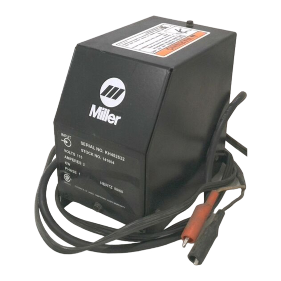
Model: PSA-2
1.
Specifications
Ref. ST-143 353-C
2.
Safety Symbol Definitions
Means Warning! Watch Out! There are possible hazards
with this procedure! The possible hazards are shown in
the adjoining symbols.
Beware of electric shock from welding electrode or wiring.
Touching the electrode while in contact with the work or
ground can cause electric shock. Always wear dry
gloves. Keep all panels and covers closed.
3.
Installation Onto Wire Feeder
Tools Needed:
3/8 in
115 To 24 Volts AC Power Supply Adapter (PSA)
For Connecting GMAW Wire Feeder To Welding Power Source
24 Volts AC, 8 Amperes Output; Nominal 110 Volts AC Input Power
Overload Protection; 14-Socket Wire Feeder Receptacle
Includes Mounting Bracket And 115 Volts AC/Remote Contactor Cord
2
OM‐542
2009−01
Have only trained and qualified persons install, operate,
or service this unit. Call your distributor if you do not un-
derstand the directions. For WELDING SAFETY and
EMF information, read wire feeder and welding power
source manuals.
Wear safety glasses with side shields.
!
1
2
1
Remove side brackets. Install
adapter into spool support using
hardware removed
brackets.
122 218E
Disconnect power before in-
stalling.
Side Brackets
Spool Support
from
side
ST-143 460-C
©
2009 MILLER Electric Mfg. Co.
Advertisement
Table of Contents

Subscribe to Our Youtube Channel
Related Manuals for Miller PSA-2


Summary of Contents for Miller PSA-2
- Page 1 Keep all panels and covers closed. Installation Onto Wire Feeder Disconnect power before in- stalling. Side Brackets Spool Support Remove side brackets. Install adapter into spool support using hardware removed from side brackets. Tools Needed: 3/8 in ST-143 460-C © 2009 MILLER Electric Mfg. Co.
- Page 2 Installation Onto Welding Power Source Disconnect power before in- stalling. Mount adapter so it does not cover labels or air louvers on welding power source. Top Mount Screws From Welding Power Source Supplied Grommets Bracket Locking Nut Supplied Screws Top Mount: Insert grommets into bracket, and install adapter using one or two screws as shown.
- Page 3 Connections And Circuit Breaker CB1 Disconnect power before in- stalling. Standard Connections Connections For 115 Volts AC/Remote Contactor Plug And Cord 115 Volts AC/Remote Contac- tor Plug Use to make 115 volts AC/remote contactor connections. Remote 14 Receptacle Use to make 24 volts AC input pow- er connection to wire feeder.
- Page 4 Troubleshooting Trouble No weld output. Remedy Be sure welding power source Power switch is On. Check cord connections or replace cords, if necessary. Reset circuit breaker CB1 (see Section 5). Check welding gun and/or wire feeder. SA-143 280-C Parts List ST-148 377-C Item Part...
Need help?
Do you have a question about the PSA-2 and is the answer not in the manual?
Questions and answers