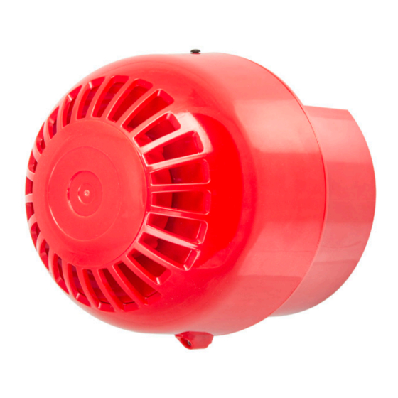
Summary of Contents for MOFLASH SIGNALLING S00608
- Page 1 INSTALLATION & TECHNICAL INFORMATION PLEASE READ PRIOR TO INSTALLATION Moflash Intrinsically Safe Sounder Range S00608, Issue 8, 19/10/2021 AUDIBLE SIGNALLING DEVICES APPROVALS AND CONFORMITIES www.moflash.com technical@moflash.co.uk...
- Page 2 3.0 Types of Approval and Standards Applied The Moflash IS Sounder product has been approved to the following standards: IEC 60079-0:2011 / EN 60079-0:2018 IEC 60079-11:2011 / EN 60079-11:2012 EN 54-3 (Approval with BRE Global) S00608 Issue 8...
- Page 3 IIIA Fibres and Flying, IIIB Flour and Grain, IIIC Coal Dust and Metal Dust. The maximum surface temperature of the product during operation will not exceed 85°C. A Declaration of Conformity and also the Sounder Range ATEX and IECEX Certificates are available on request or alternately visit www.moflash.com S00608 Issue 8...
- Page 4 General Requirement The Sounder must be installed in accordance with the latest EN60079-0 specification or equivalent IEC specification, with consideration for any local installation requirements, and should only be carried out by appro- priately competent and qualified personnel. S00608 Issue 8...
- Page 5 Select tone by configuring the DIP switches in the head unit. The tone table can be found on page 12 of this booklet (Pre-set to tone 18). • Relocate head onto mounted base unit & rotate clockwise until locked in place. S00608 Issue 8...
- Page 6 To control the Sounder use either a switch in the safe area on either the positive or negative lines into the Barrier, or by turning the power supply on and off ,this is shown at the top of page 7. S00608 Issue 8...
- Page 7 For this application, a barrier with 2 Diode return paths is required as shown in the diagram below: Switching between return paths for the 2 stage system will enable the 2nd tone. Second stage tone can be found in the table on page 12. S00608 Issue 8...
- Page 8 As with all equipment in the system, the correct ratings must be main- tained to keep the integrity and safety to the correct levels. The relay can be switched to change between stage 1 and stage 2. S00608 Issue 8...
- Page 9 If required, an external switch can be wired in series with the (1) and/or (2) connections to give independent remote change over from 1 stage to 2 stage tones. This switch must conform to Intrinsically Safe installation (EN 60079-0:2012 + A11:2013, EN 60079-11:2012, EN 50303:2000). S00608 Issue 8...
- Page 10 3x M20 knockouts for wiring in purposes, and only those required should be used. Any that are removed must have at least an IP66 rated gland fitted with cable passing through it or suitable plug. *= meets the IP33C requirements of EN 54-3:2001+A1:2002+A2:2006. S00608 Issue 8...
- Page 11 IEC 60079-14 and IEC 60079-25 and that capacitance and inductance limits are not exceeded by distributed capacitance (Cc) or distributed inductance (Ic) due to cable length. Table of Entity Parameters Parameter Barrier Supply 93 mA 660 mW S00608 Issue 8...
- Page 12 I - I - I - I - I - O Note:EN54-3 Compatible Tones are 1,2,3,6,7 & 13 All dB readings have been taken with Intrinsically safe barrier in place, dB readings are ±3dB(A). For EN54-3 Sound Pressure Level Data see Document MOIS02 S00608 Issue 8...


Need help?
Do you have a question about the S00608 and is the answer not in the manual?
Questions and answers