
Related Manuals for MOFLASH SIGNALLING IS-S-02


Summary of Contents for MOFLASH SIGNALLING IS-S-02
- Page 1 INSTALLATION & TECHNICAL INFORMATION PLEASE READ PRIOR TO INSTALLATION Moflash Intrinsically Safe Sounder Range S00608, Issue 7, 28/07/2020 AUDIBLE SIGNALLING DEVICES APPROVALS AND CONFORMITIES Website: www.moflash.com Email: technical@moflash.co.uk...
- Page 2 1.0 Introduction The Moflash Intrinsically Safe Sounder product (IS-S-02) is ATEX and IECEx certified. The Sounder is approved to be installed in Groups I (Mining) and Group II (above ground), Zones 0, 1 or 2 with gas groups IIA, IIB, IIC and Zones 20, 21 and 22 for dust groups IIIC and carries a temperature classification of T6.
- Page 3 4.0 Zones, Gas Groups and Temperature Classifications The Moflash Intrinsically Safe Sounder is certified to the following: Ex ia IIC T6 Ga, Ex ia IIIC T85C Da, Ex ia I Ma. This means that the units can be installed in locations with the following condi- tions when connected to an approved system: Zones Zone 0...
-
Page 4: Installation
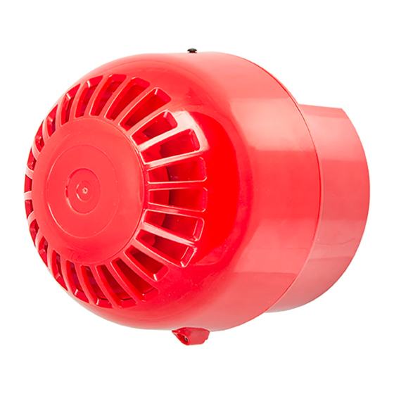
5.0 Installation The TimeSaver base enables quick and easy installation of these units with no extra cabling to be made to the head of the unit. Connections are made to the base during the initial wiring phase which results in faster and more reliable in- stallation. - Page 5 • The location of the Sounder should be chosen with due regard to the area over which the signalling device must be audible. • These units are suitable for wall or ceiling mount only. • Environmental exposure conditions during installation should be dry. Moist or wet conditions should be avoided.
- Page 6 Negative Supply Single Stage Alarm Before final installation of the IS-S-02 Sounder head unit onto the installed base the alarm tone must be set (see page 5). To control the Sounder use either a switch in the safe area on either the positive or negative lines into the Barrier, or by turning the power supply on and off ,this is shown at the top of page 7.
- Page 7 Two Stage Alarm When a two stage alarm is required it is possible to activate an alternate tone by connecting the “♫/☼” (Beacon ground) pin to 0v (as detailed in the table on page 5). For this application, a barrier with 2 Diode return paths is required as shown in the diagram below: Switching between return paths for the 2 stage system will enable the 2nd tone.
-
Page 8: Galvanic Isolator
Barriers. These Isolators are often more expensive per unit but may reduce installation costs as the earth is not required. The IS-S-02 range can be powered by the Galvanic Isolators with matching pa- rameters as described in the entity parameters section of the installation sheet. - Page 9 End of line monitoring is applicable to the Sounder Product. For this to func- tion correctly the resistor must be connected between the IN+ terminal and the Sounder Negative Supply. A suitable Zener Barrier which can allow reverse polarity monitoring to take place and a fire panel compatible with Intrinsically Safe products must also be used.
- Page 10 7.0 Maintenance Little or no maintenance is required during the normal working life of the product. The Moflash Intrinsically Safe enclosures are resistant to most acids, alkalis and chemicals and have been designed to withstand severe weather conditions. However it is suggested that continuous supervision and periodic inspections may be required in relation to the requirements of the installation as per IEC 60079-17.
- Page 11 As previously stated in the installations sheet, the Intrinsically Safe Sounder Range must be powered via a suitable Zener Barrier or Galvanic Isolator whose characteristics do not exceed: Uo:28v, Io: 93mA, Po:660mW The value for Uo must be between 16v and 28v, and Io should not be below 50mA.
- Page 12 9.0 Tone Table DIP SWITCH TONE TONE TYPE TONE DESCRIPTION/ APPLICATION 2nd Stage dB(A) @ 1m 1 - 2 - 3 - 4 - 5 - 6 970Hz O - O - O - O - O - O 800Hz/970Hz @ 2Hz O - O - O - O - I - O 800Hz –...
Need help?
Do you have a question about the IS-S-02 and is the answer not in the manual?
Questions and answers