Table of Contents
Advertisement
Quick Links
Advertisement
Table of Contents

Subscribe to Our Youtube Channel
Related Manuals for SPL Madison 1260


Summary of Contents for SPL Madison 1260
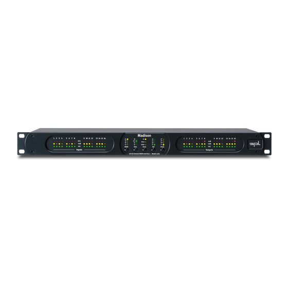
- Page 1 Manual Madison Model 1260 16+16 Channel MADI-Interface...
-
Page 2: Table Of Contents
Content Manual Madison Declaration of CE Conformity Notes on Environmental Protection Contact Scope Of Delivery Symbols and Notes Introduction Welcome Made in Germany. With Passion. Support The Madison in six seconds Important Security Advices Madison... - Page 3 Content Hook Up Placement Rack Mounting Air Circulation Before Connecting to the Power Outlet Signal Connections Rear Panel: Switches On/Off Switch Rear Panel: Digital Connections USB Port Clock MADI Input and Output Rear Panel: Analog Connections DB25 sockets: Inputs 1-8 and 9-16 DB25 sockets: Outputs 1-8 and 9-16 DB25 sockets: Pin Wiring (TASCAM-Standard) Rear Panel/Wiring Diagram...
-
Page 4: Manual Madison
This document is the property of SPL and may not be copied or reproduced in any manner, in part or fully, without prior authorization by SPL. -
Page 5: Scope Of Delivery
The symbol of a lamp directs your attention to explanations of important functions or appli- cations. Attention: Do not attempt any alterations to this device without the approval or supervision of SPL electronics GmbH. Doing so could void completely any and all of your warranty rights and claims to user support. Scope Of Delivery The scope of delivery comprises the Madison, the power cord, the guarantee card and this manual. -
Page 6: Introduction
Made in Germany. With Passion. The SPL team surely hopes you like this unit as much as we like you for buying it. There is a lot of passion, brains and time put into this unique analog and digital device and we really can‘t wait to hear back from you and get all the details on how you use the Madison and how satis- fied you are with it. -
Page 7: The Madison In Six Seconds
• 16 Channel bi-directional digital/analog converter with SPL sound • Digital MADI IO (max. 64 Ins and 64 Outs) • Analog IO: Mastering-grade, fully balanced SPL AD/DA converters, 16 Ins and 16 Outs, unique SPL 36V Rail analog technology • Reference/Studio Level: full 24dBu, or +22dBu, +18dBu and +15dBu •... -
Page 8: Important Security Advices
Opening the unit: Simply put: DON‘T, if you are not a certified SPL technician or engineer. Really: Do not open the device housing, as there is great risk you will damage the device, or –... -
Page 9: Hook Up
Hook Up Placement Place the unit on a leveled and stable surface or mount it in a dedicated rack frame. The unit’s enclosure is EMC-safe and effectively shielded against HF interference. Nonetheless, you should carefully consider where you place the unit to avoid electrical distur- bances. -
Page 10: Rear Panel: Switches
Madison whenever such updates become available. Information on how to process such updates are given with the update files. The USB port may also be utilized as a service port for SPL engineers. Clock Provides Wordclock I/O, including a termination switch for the Wordclock input. The termina- tion switch should be engaged if there is no connection present on the Wordclock input and the Wordclock output is used to clock an external device. -
Page 11: Rear Panel: Analog Connections
1-14 are processed, while CH 15 and 16 remain inactive (ssee „MADI Modes 56 CH and 64 CH“ on page 13). All individual analogue channels are fully balanced and powered by SPL‘s unique 36V rail technology. DB25 sockets: Outputs 1-8 and 9-16 The 16 Analogue Outputs are connected via two DSUB 25 eight-channel connectors, that comply to the TASCAM (R) pinout (see below). -
Page 12: Rear Panel/Wiring Diagram
Rear Panel/Wiring Diagram Madison... -
Page 13: Operation
Operation MADI Modes 56 CH and 64 CH Since MADI was invented in the early 1990‘s (AES10-1991), the industry forced a couple of evolutional changes on the standard (AES 10-2003) to adapt to the broad digitalization of audio production in general. Today, two general MADI modes are known: 56CH and 64CH;... -
Page 14: Madi Modes And Madi Frame Sizes
Operation MADI Modes and MADI Frame Sizes The following diagram shows one audio frame at different sample rates and MADI modes. The numbers inside the cells represent the MADI channels. The area of the frame remains the same, regardless of whether several slots are used or the slot bandwidth “b“... -
Page 15: Control Elements
Control Elements MADI Button Use the MADI Button in order to select one of the modes described in the previous chapter „Operation“. Press the button to toggle between modes, the above LEDs indicate which mode is selected. With sample rates of 44.1 to 48kHz you can only toggle between 56Ch and 64Ch MADI mode (Hi and Lo Speed are only selcetable at double or quad sample rates). -
Page 16: Clock Button
The clock of the Madison can be set to its own internal high-precision clock, generated by our ultra-low jitter SPL Clock Shop, which then becomes the clock Master of the complete digital system connected to it. All other digital devices connected to the Madison need to slave to this clock (by connecting to the Madison’s Wordclock or MADI Out). -
Page 17: Chain Button
Control Elements CHAIN Button With the Chain Button the user can determine the position of a unit within the chain. Up to four units can be daisy-chained over MADI in order to connect multiple Madisons to one MADI device. MADI can transport: •... -
Page 18: Madi Wiring In A Daisy-Chain
Control Elements MADI Wiring in a Daisy-Chain To MADI input of an external unit Unit 4 (Chain: 4th) MADI channels 49-64 Unit 3 (Chain: 3rd) MADI channels 33-48 Unit 2 (Chain: 2nd) MADI channels 17-32 Unit 1 (Chain: 1st) MADI channels 1-16 From MADI output of an external unit Important Notes for a Madison Chain... -
Page 19: Input And Output Meters
Control Elements Input and Output Meters The metering system for the Madison inputs and outputs measures the peaks in the digital domain (Post AD and Pre DA). The meters are organized in blocks of four by four channels. Since the human brain can differ- entiate an amount of four without using much brain power, it is easy —... -
Page 20: Specifications
Reference Levels/Inputs 24dBu max, selectable 22dBu, 18dBu, 15dBu Reference Levels/Outputs 24dBu max, selectable 22dBu, 18dBu, 15dBu Clock Internal clock circuitry from SPL, Wordclock or MADI Expandability 4 units via MADI chain for 64 channels Wordclock Input 75 ohms, terminated impedance Wordclock Level Input: TTL/CMOS5/CMOS3;... -
Page 21: Your Notes
Your Notes .............. - Page 22 Your Notes ..............
- Page 23 Your Notes ..............
- Page 24 Manual Madison < english Madison...
Need help?
Do you have a question about the Madison 1260 and is the answer not in the manual?
Questions and answers