
Subscribe to Our Youtube Channel
Related Manuals for SPL DynaMaxx 9735


Summary of Contents for SPL DynaMaxx 9735
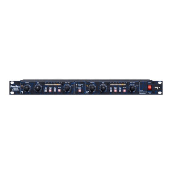
- Page 1 DynaMaxx Manual Compressor, Limiter, Noise Gate and De-Compressor model 9735 SOUND PERFORMANCE LAB...
- Page 2 Changes without notice. This document is the property of SPL and may not be copied or reproduced in any manner, in part or full without the authorisation of SPL.
-
Page 3: Table Of Contents
Specifications ...................19 Warranty ....................20 Dear customer, Foreword Thank you for the confidence you have shown towards SPL elec- tronics GmbH by purchasing the SPL D .You have decided to use a tool of high performance which sets you in the position to have faster success and a better sound quality in your music productions, live sound applications and pre-masterings. -
Page 4: Introduction
THAT 2181 VCAs, and the is the first compressor circuit actually uses two of these excellent VCAs in SPL’s Double to use the new THAT 2181 VCAs VCA-Drive mode configuration, which doubles the operating –... -
Page 5: Operation Safety
DE-COMPRESSION: Regain vitality and dynamics converts the compressor to an intelligent upward expander that from highly compressed allows you the de-compress highly compressed audio signals, audio files such as samples, keyboards sounds or previously recorded tracks that have been overcompressed. For example, the sounds used in most drum machines are highly compressed, but processing them via the De-compress mode restores their dynamics and vitality. -
Page 6: Connections
(jack or XLR) should be connected at a time – the D is not intended to be used as a mixer! To ensure optimal signal quality, SPL has developed a new hybrid-component balanced input/output stage using all laser- trimmed resistors with a tolerance of 0.01%. This approach has resulted in an exceptionally high CCMR (common mode rejection: -80 dB at 1kHz). -
Page 7: Tech Talk
Tech Talk This section deals with the technical background of the and explains why we felt it necessary to do some things rather differently to the way other manufacturers do them. We will also explain the benefits of the D design. -
Page 8: Full-Band Versus Multi-Band
Multi-band compressors split Full-Band versus Multi-Band the input in several bands to Some compressors try to solve the problem of high frequencies overcome pumping effects. being modulated by low frequency compression by moving to a Mixing the bands back split band system, so why don't we do that? together creates phase inter- Multi-band compression seems like a good idea to overcome modulations resulting in... - Page 9 any closely following notes will suffer increased transient distor- - Attack too fast: adds distor- tion because the control voltage within the compressor rises tion plus “surfing“-effects further as successive notes are processed.This behaviour is some- - Attack too slow: peaks slip times described as ‘surfing’...
-
Page 10: Dynamic Intelligence: Release Time Automation
Dynamic intelligence: Release time automation How does DynaMaxx adjust the Release time? Again, it is beneficial to look at what happens when the Release time is too short: In this case the compressor will restore normal gain conditions as soon as the peak has passed, and this rapid increase in gain is what we call breathing. -
Page 11: Double Vca-Drive Technology
SPL’s Double VCA Drive Technology Double VCA Drive Technology utilizes two VCAs per audio channel, where one VCA handles positive current and the other negative. This way, the control voltage can effectively be halved, but the amount of gain change can be doubled. The benefit of this configuration is that the transistors within the VCAs don’t run... -
Page 12: Control Elements
Control Elements Active The ACTIVE switch operates a hard-bypass relay circuit to switch the channel in and out of processing and a status LED indicates that the channel is active. Relay hard-bypass XLR and jack The unit also switches to relay hard-bypass automatically in the inputs and outputs case of a power failure, either on the primary or secondary side of the power supply, or when the unit is turned off at the POWER... -
Page 13: Gain
As with any compressor, the overall signal level decreases with increasing compression, so the GAIN control is used to compen- sate for this (also see 4). To compare input and output levels more accurately, monitor a precise PPM metering and set the GAIN control to a position where both the input and output peak levels are identical. -
Page 14: Soft Limit
Gain Turn the GAIN control clockwise until the peak level of the input is the same as the peak level of the output. If you use D a premastering application, you can use the LED display to evaluate the increase in subjective loudness. To do this, locate the highest peak level within the source material, and after having applied the desired degree of compression, set the GAIN control so that the peak level is reduced to 0 dB. -
Page 15: Effect-Compression
Effect Comp. The EFFECT-COMPRESSION function applies a fixed Release time of 60ms, but the Attack time is still automated. This mode increases the perceived loudness in comparison with the normal Compression mode, and audible compression artifacts can be generated for creative purposes. The gain of the audio signal is restored to normal shortly after the 60 ms Release time has passed, creating deliberate breathing and pumping effects. - Page 16 De-Compression Also the intonation of a Kick Drum is improved resulting in a better grooving rhythm. Remember that the operation of the GAIN control (4) is inverted when the DE-COMPRESSION mode is active.Turning the GAIN control clockwise lowers the output level to compensate for the level increase.
-
Page 17: Led-Display
Both channels of the D are equipped with a 20-digit LED display LED ladder meter capable of displaying gain changes to a resolu- tion of 1dB over the range -10dB to +9dB. When applying compression to the audio signal, the LED meter displays the amount of gain reduction taking place along with any gain compensation due to the GAIN control. -
Page 18: Stereo Couple
Stereo Couple When processing stereo material, the STEREO COUPLE function should be switched on so that both channels produce the same degree of gain change, regardless of any difference in levels of the two channels. This is necessary to maintain a coherent and stable stereo image. -
Page 19: Power Supply
Power Supply Special care has gone into the design of the power supply of the D because the power supply is the heart of any elec- tronic system, and the better it is, the better the whole system works. In an audio system, this translates into better sound quality, lower noise and lower distortion. -
Page 20: Specifications
Specifications Input & Output Instrumentation amplifier, electronically balanced (differential), transformerless Nominal input level ......... +6 dB Input impedance ..........= 22 kOhms Output impedance .......... < 600 Ohms Max. input level ..........+24 dBu Max. output level ..........+22,4 dBu Minimum load ohms ........ -
Page 21: Warranty
The specific period of this limited warranty shall be that which is described to the original retail purchaser by the authorized SPL dealer or distributor at the time of purchase. SPL does not, however, warrant its products against any and all...
Need help?
Do you have a question about the DynaMaxx 9735 and is the answer not in the manual?
Questions and answers