Table of Contents
Advertisement
Quick Links
Advertisement
Table of Contents

Related Manuals for Lenovo 7D9E


Summary of Contents for Lenovo 7D9E
- Page 1 ThinkSystem SR655 V3 System Configuration Guide Machine Types: 7D9E, 7D9F...
- Page 2 Before using this information and the product it supports, be sure to read and understand the safety information and the safety instructions, which are available at: http://thinksystem.lenovofiles.com/help/topic/safety_documentation/pdf_files.html In addition, be sure that you are familiar with the terms and conditions of the Lenovo warranty for your server, which can be found at: http://datacentersupport.lenovo.com/warrantylookup Second Edition (April 2023) ©...
-
Page 3: Table Of Contents
Safety ....iii Identify the server and access the Lenovo XClarity Safety inspection checklist ... iv Controller . - Page 4 ThinkSystem SR655 V3 System Configuration Guide...
-
Page 5: Safety
Vor der Installation dieses Produkts die Sicherheitshinweise lesen. Prima di installare questo prodotto, leggere le Informazioni sulla Sicurezza. Les sikkerhetsinformasjonen (Safety Information) før du installerer dette produktet. Antes de instalar este produto, leia as Informações sobre Segurança. © Copyright Lenovo 2023... -
Page 6: Safety Inspection Checklist
1 & IEC 60950-1, the standard for Safety of Electronic Equipment within the Field of Audio/Video, Information Technology and Communication Technology. Lenovo assumes you are qualified in the servicing of equipment and trained in recognizing hazards energy levels in products. Access to the equipment is by the use of a tool, lock and key, or other means of security, and is controlled by the authority responsible for the location. - Page 7 Click Power ➙ Power Cables to see all line cords. • Make sure that the insulation is not frayed or worn. 3. Check for any obvious non-Lenovo alterations. Use good judgment as to the safety of any non-Lenovo alterations.
- Page 8 ThinkSystem SR655 V3 System Configuration Guide...
-
Page 9: Chapter 1. Introduction
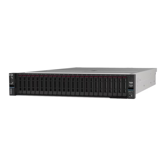
Chapter 1. Introduction The ThinkSystem SR655 V3 server (7D9E and 7D9F) is a 1-socket 2U server that features the 4th generation EPYC processor family of AMD. The server offers a broad selection of drive and slot configurations, high performance, and expansion for various IT workloads. Combining performance and flexibility, the server is a great choice for enterprises of all sizes. -
Page 10: Tech Tips
RAID levels 0, 1, 5, 6, 10, 50, and 60. Tech Tips Lenovo continually updates the support website with the latest tips and techniques that you can use to solve issues that your server might encounter. These Tech Tips (also called retain tips or service bulletins) provide procedures to work around issues or solve problems related to the operation of your server. -
Page 11: Technical Specifications
• Operating systems Technical specifications Summary of the technical specifications of server. Depending on the model, some features might not be available, or some specifications might not apply. The latest specifications information is always available at https://lenovopress.lenovo.com/ Processor Supports fourth-generation AMD ®... - Page 12 • Lenovo XClarity Controller (XCC), which provides service processor control and monitoring functions, video controller, and remote keyboard, video, mouse, and remote drive capabilities. – The server supports Lenovo XClarity Controller 2 (XCC2). For additional information about Lenovo XClarity Controller 2 (XCC2), refer to https://sysmgt.lenovofiles.com/help/topic/lxcc_frontend/lxcc_overview.html...
-
Page 13: Mechanical Specifications
• Microsoft Windows Server • VMware ESXi References: • Complete list of available operating systems: https://lenovopress.lenovo.com/osig • OS deployment instructions, see “Deploy the operating system” on page Mechanical specifications Summary of the mechanical specifications of server. Depending on the model, some features might not be available, or some specifications might not apply. -
Page 14: Environmental Specifications
Lenovo recommends that you consult with qualified experts in this field to determine whether you are in compliance with the applicable regulations. - Page 15 Environment ThinkSystem SR655 V3 complies with ASHRAE Class A2 specifications with most configurations, and depending on the hardware configuration, also complies with ASHRAE Class A3, and Class A4 specifications. System performance may be impacted when operating temperature is outside ASHRAE A2 specification. Depending on the hardware configuration, SR655 V3 server also complies with ASHRAE Class H1 specification.
- Page 16 If Lenovo determines that the levels of particulates or gases in your environment have caused damage to the device, Lenovo may condition provision of repair or replacement of devices or parts on implementation of appropriate remedial measures to mitigate such environmental contamination.
-
Page 17: Management Options
Consolidates the service processor functionality, Super I/O, video controller, and remote presence capabilities into a single chip on the server system board (system board assembly). Interface • CLI application Lenovo XClarity Controller • Web GUI interface • Mobile application • REST API Usage and downloads https://sysmgt.lenovofiles.com/help/topic/lxcc_frontend/lxcc_overview.html... - Page 18 Important: Lenovo XClarity Provisioning Manager (LXPM) supported version varies by product. All versions of Lenovo XClarity Provisioning Manager are referred to as Lenovo XClarity Provisioning Manager and LXPM in this document, unless specified otherwise. To see the LXPM version supported by your server, go to https:// sysmgt.lenovofiles.com/help/topic/lxpm_frontend/lxpm_product_page.html...
- Page 19 1. Most options can be updated through the Lenovo tools. Some options, such as GPU firmware or Omni- Path firmware require the use of supplier tools. 2. The server UEFI settings for option ROM must be set to Auto or UEFI to update firmware using Lenovo XClarity Administrator, Lenovo XClarity Essentials, or Lenovo XClarity Controller.
- Page 20 ThinkSystem SR655 V3 System Configuration Guide...
-
Page 21: Chapter 2. Server Components
“Front I/O module (on media bay)” on page 15 “Rack latch (right)” on page 15 “Pull-out information tab” on page 15 “Drive bays” on page 14 “Rack latch (left)” on page 15 Front view with sixteen 2.5-inch front drive bays © Copyright Lenovo 2023... - Page 22 Table 3. Components on the front of the server Callout Callout “External diagnostics connector (optional)” on page 15 “VGA connector (optional)” on page 15 “Drive activity LED” on page 14 “Drive status LED” on page 14 “Front I/O module (on media bay)” on page 15 “Rack latch (right)”...
-
Page 23: Front I/O Module
“Front I/O module” on page Pull-out information tab The Lenovo XClarity Controller network access label is attached on the pull-out information tab. The default Lenovo XClarity Controller hostname and the IPv6 Link Local Address (LLA) are provided on the tab. - Page 24 Front I/O module (on rack latch) Front I/O module (on media bay) Table 5. Components on the front I/O module Callout Callout USB 3 (5 Gbps) connector USB 2.0 connector Power button with power status LED Network activity LED (for OCP module) System ID button with system ID LED System error LED Front operator panel...
- Page 25 ID button, the state of the system ID LED changes. The LED can be changed to on, blinking, or off. You can also use the Lenovo XClarity Controller or a remote management program to change the state of the system ID LED to assist in visually locating the server among other servers.
-
Page 26: Rear View
The hot-swap redundant power supply units help you avoid significant interruption to the operation of the system when a power supply unit fails. You can purchase a power supply option from Lenovo and install the power supply unit to provide power redundancy without turning off the server. -
Page 27: Top View
NMI button Use this button only when you are directed to do so by Lenovo Support. Press this button to force a nonmaskable interrupt (NMI) to the processor. By this way, you can make the operating system halt (such as Windows Blue Screen of Death) and take a memory dump. -
Page 28: System-Board-Assembly Layout
Figure 5. Server top view Table 7. Component identification (top view) Front backplane(s) Intrusion switch System fans Memory modules Processor and heat sink Riser assemblies Power supply unit system board assembly Note: The illustration shows the server rear configuration with two riser assemblies. The server rear configurations vary by server model. -
Page 29: System-Board-Assembly Connectors
Figure 6. System-board-assembly layout System I/O board Firmware and RoT security module Processor board Fan board Power inverter board (PIB) For information about the LEDs that are available on the system board assembly, see: • “System-board-assembly LEDs” on page 41 •... - Page 30 Figure 7. System-board-assembly connectors Table 8. System-board-assembly connectors NMI button Rear USB connector Micro SD connector VGA connector Serial port connector Rear USB connectors Lift handle XCC system management port Internal USB connector Second management Ethernet connector Riser 1 slot OCP module connector CMOS battery (CR2032) M.2 power connector...
-
Page 31: System-Board-Assembly Switch
Table 8. System-board-assembly connectors (continued) Backplane 2 power connector PCIe connector 7 / SATA connector 0 PCIe connector 3 PCIe connector 4 PCIe connector 2 PCIe connector 1 Backplane 1 power connector Front VGA connector External LCD connector Pump connector Fan board sideband connector Fan board power connector Internal RAID power connector... - Page 32 Figure 8. Switch block on the system board assembly Table 9. Switch block on the system board assembly Switch Default position Description number Switch name SW5-1 Force BMC CPU Forces BMC and CPU into reset when changing it to reset the ON position.
-
Page 33: System Leds And Diagnostics Display
System LEDs and diagnostics display See the following section for information on available system LEDs and diagnostics display. • “Drive LEDs” on page 25 • “Front operator panel LEDs” on page 25 • “External diagnostics handset” on page 32 • “XCC system management port LEDs”... - Page 34 Figure 10. Front operator panel LEDs Power button with power status LED (green) Network activity LED (green) System ID button with system ID LED (blue) System error LED (yellow) Power button with power status LED (green) You can press the power button to power on the server when you finish setting up the server. You also can hold the power button for several seconds to power off the server if you cannot shut down the server from the operating system.
-
Page 35: Integrated Diagnostics Panel
ID button, the state of the system ID LED changes. The LED can be changed to on, blinking, or off. You can also use the Lenovo XClarity Controller or a remote management program to change the state of the system ID LED to assist in visually locating the server among other servers. - Page 36 Diagnostics panel overview The diagnostics device consists of an LCD display and 5 navigation buttons. LCD display Scroll buttons (up/down/left/right) Press the scroll buttons to locate and select system information. Select button Press the select button to select from the options in the menu.
- Page 37 Full menu list Following is the list of options available on the diagnostics panel/handset. Switch between an option and the subordinate information entries with the select button, and switch among options or information entries with the scroll buttons. Depending on the model, the options and entries on the LCD display might be different. Chapter 2 Server components...
- Page 38 Home Menu (System Status Dashboard) Home Menu Example System name System status Active alert quantity Temperature Power consumption Checkpoint code Active Alerts Sub Menu Example Home screen: Active error quantity Note: The “Active Alerts” menu displays only the 1 Active Alerts quantity of active errors.
- Page 39 System Firmware Sub Menu Example UEFI UEFI (Inactive) • Firmware level (status) Build: D0E101P • Build ID Version: 1.00 • Version number Date: 2019-12-26 • Release date XCC Primary XCC Primary (Active) • Firmware level (status) Build: DVI399T • Build ID Version: 4.07 •...
-
Page 40: External Diagnostics Handset
System Environmental Information Sub Menu Example Ambient Temp: 24 C PSU1: Vin= 213 w • Ambient temperature Inlet= 26 C • PSU status FAN1 Front: 21000 RPM • Spinning speed of fans by RPM FAN2 Front: 21000 RPM FAN3 Front: 21000 RPM FAN4 Front: 21000 RPM Active Sessions Example... - Page 41 Location of the external diagnostics handset Description Location The external diagnostics handset is connected to the External diagnostics handset server with an external cable. Magnetic bottom With this component, the diagnostics handset can be attached to the top or side of the rack with hands spared for service tasks.
- Page 42 LCD display Scroll buttons (up/down/left/right) Press the scroll buttons to locate and select system information. Select button Press the select button to select from the options in the menu. ThinkSystem SR655 V3 System Configuration Guide...
- Page 43 Options flow diagram The LCD panel displays various system information. Navigate through the options with the scroll keys. Depending on the model, the options and entries on the LCD display might be different. Chapter 2 Server components...
- Page 44 Full menu list Following is the list of options available on the diagnostics panel/handset. Switch between an option and the subordinate information entries with the select button, and switch among options or information entries with the scroll buttons. Depending on the model, the options and entries on the LCD display might be different. Home Menu (System Status Dashboard) Home Menu Example...
- Page 45 System Firmware Sub Menu Example UEFI UEFI (Inactive) • Firmware level (status) Build: D0E101P • Build ID Version: 1.00 • Version number Date: 2019-12-26 • Release date XCC Primary XCC Primary (Active) • Firmware level (status) Build: DVI399T • Build ID Version: 4.07 •...
-
Page 46: Xcc System Management Port Leds
System Environmental Information Sub Menu Example Ambient Temp: 24 C PSU1: Vin= 213 w • Ambient temperature Inlet= 26 C • PSU status FAN1 Front: 21000 RPM • Spinning speed of fans by RPM FAN2 Front: 21000 RPM FAN3 Front: 21000 RPM FAN4 Front: 21000 RPM Active Sessions Example... -
Page 47: Power Supply Leds
Description Ethernet port Use this green LED to distinguish the network connectivity status: link LED • Off: The network link is disconnected. • Green: The network link is established. Ethernet port Use this green LED to distinguish the network activity status: activity LED •... - Page 48 When the power load increases, the standby power supply will switch to active state to provide sufficient power to the server. To disable zero-output mode, log in to the Lenovo XClarity Controller web interface, choose Server Configuration ➙ Power Policy, disable Zero Output Mode, and then click Apply. If you disable zero-output mode, both power supplies will be in the active state.
-
Page 49: System-Board-Assembly Leds
System-board-assembly LEDs The following illustration shows the light-emitting diodes (LEDs) on the system board assembly that contains the system I/O board and processor board. Figure 13. System-board-assembly LEDs Table 10. System-board-assembly LEDs Description Action System error LED LED on: An error has occurred. Check system logs or internal error LEDs to identify the (yellow) failed part. - Page 50 RoT security module are installed correctly. (Trained technician only) Reinstall them if needed. 3. If the problem remains, contact Lenovo Support. FPGA heartbeat The FPGA heartbeat LED helps If the FPGA heartbeat LED is always off or always on, do LED (green) you identify the FPGA status.
-
Page 51: Leds On The Firmware And Rot Security
3. (Trained technician only) If the problem remains, available at: YouTube capture FFDC log, and replace the processor board. 4. If the problem still remains, contact Lenovo Support. DIMM error LEDs LED on: an error has occurred to For more information, see “Memory problems” in User (Amber) the DIMM the LED represents. - Page 52 Table 11. LEDs description (continued) Fatal FPGA Actions Scenario Error heartbeat heartbeat note note Blink Replace the firmware and RoT security module. Blink Replace the firmware and RoT security module. No system power If the AC power is on, but the (FPGA heartbeat system board assembly does LED off)
-
Page 53: Chapter 3. Parts List
Tier 1 CRU at your request with no service agreement, you will be charged for the installation. • Tier 2 customer replaceable unit (CRU): You may install a Tier 2 CRU yourself or request Lenovo to install it, at no additional charge, under the type of warranty service that is designated for your server. - Page 54 • Consumable and Structural parts: Purchase and replacement of consumable and structural parts (components, such as a filler or bezel) is your responsibility. If Lenovo acquires or installs a structural component at your request, you will be charged for the service.
-
Page 55: Power Cords
Several power cords are available, depending on the country and region where the server is installed. To view the power cords that are available for the server: 1. Go to: http://dcsc.lenovo.com/#/ 2. Click Preconfigured Model or Configure to order. 3. Enter the machine type and model for your server to display the configurator page. - Page 56 • For units intended to be operated at 115 volts: Use a UL-listed and CSA-certified cord set consisting of a minimum 18 AWG, Type SVT or SJT, three-conductor cord, a maximum of 15 feet in length and a parallel blade, grounding-type attachment plug rated 15 amperes, 125 volts. •...
-
Page 57: Chapter 4. Unboxing And Setup
They might be required to receive warranty service. Identify the server and access the Lenovo XClarity Controller This section contains instruction on how to identify your server and where to find the Lenovo XClarity Controller access information. -
Page 58: Server Setup Checklist
Lenovo XClarity Controller network access label In addition, the Lenovo XClarity Controller (XCC) network access label is attached to the pull-out information tab located near the lower right corner in the front of the chassis, with MAC address accessible with a pull. - Page 59 • You can press the power button. • The server can restart automatically after a power interruption. • The server can respond to remote power-on requests sent to the Lenovo XClarity Controller. Note: You can access the management processor interface to configure the system without powering on the server.
- Page 60 The following information is available for RAID configuration: • https://lenovopress.lenovo.com/lp0578-lenovo-raid-introduction • https://lenovopress.lenovo.com/lp0579-lenovo-raid-management-tools-and-resources 4. Install the operating system. 5. Back up the server configuration. 6. Install the applications and programs for which the server is intended to be used. ThinkSystem SR655 V3 System Configuration Guide...
-
Page 61: Chapter 5. System Configuration
The following methods are available to set the network connection for the Lenovo XClarity Controller if you are not using DHCP: • If a monitor is attached to the server, you can use Lenovo XClarity Provisioning Manager to set the network connection. -
Page 62: Update The Firmware
ID button. To connect using the Lenovo XClarity Administrator Mobile app: 1. Connect the USB cable of your mobile device to the Lenovo XClarity Controller USB connector on the server. 2. On your mobile device, enable USB tethering. - Page 63 Windows Server, Red Hat Enterprise Linux (RHEL) and SUSE Linux Enterprise Server (SLES) operating system distributions. Machine-type-specific firmware-only Static Bundles (Service Packs) are also available. Firmware updating tools See the following table to determine the best Lenovo tool to use for installing and setting up the firmware: Tool Update Core...
- Page 64 “Firmware Update” section in the LXPM documentation compatible with your server at https:// sysmgt.lenovofiles.com/help/topic/lxpm_frontend/lxpm_product_page.html • Lenovo XClarity Controller If you need to install a specific update, you can use the Lenovo XClarity Controller interface for a specific server. Notes: ThinkSystem SR655 V3 System Configuration Guide...
- Page 65 – If you update firmware through the Lenovo XClarity Controller, make sure that you have downloaded and installed the latest device drivers for the operating system that is running on the server. For additional information about using Lenovo XClarity Controller to update firmware, see: “Updating Server Firmware”...
-
Page 66: Configure The Firmware
Several options are available to install and set up the firmware for the server. Important: Lenovo does not recommend setting option ROMs to Legacy, but you can conduct this setting if necessary. Note that this setting prevents UEFI drivers for the slot devices from loading, which may cause negative side effects to Lenovo software, such as LXCA, OneCLI, and XCC. -
Page 67: Memory Module Configuration
OS logical drives or volumes. An introduction to RAID is available at the following Lenovo Press website: https://lenovopress.lenovo.com/lp0578-lenovo-raid-introduction Detailed information about RAID management tools and resources is available at the following Lenovo Press website: https://lenovopress.lenovo.com/lp0579-lenovo-raid-management-tools-and-resources Deploy the operating system Several options are available to deploy an operating system on the server. -
Page 68: Back Up The Server Configuration
Available tools: – Lenovo XClarity Administrator http://sysmgt.lenovofiles.com/help/topic/com.lenovo.lxca.doc/compute_node_image_deployment.html – Lenovo XClarity Essentials OneCLI http://sysmgt.lenovofiles.com/help/topic/toolsctr_cli_lenovo/onecli_r_uxspi_proxy_tool.html – Lenovo XClarity Integrator deployment pack for SCCM (for Windows operating system only) https://sysmgt.lenovofiles.com/help/topic/com.lenovo.lxci_deploypack_sccm.doc/dpsccm_c_endtoend_ deploy_scenario.html • Single-server Available tools: – Lenovo XClarity Provisioning Manager “OS Installation” section in the LXPM documentation compatible with your server at https:// sysmgt.lenovofiles.com/help/topic/lxpm_frontend/lxpm_product_page.html... -
Page 69: Appendix A. Getting Help And Technical Assistance
Appendix A. Getting help and technical assistance If you need help, service, or technical assistance or just want more information about Lenovo products, you will find a wide variety of sources available from Lenovo to assist you. On the World Wide Web, up-to-date information about Lenovo systems, optional devices, services, and support are available at: http://datacentersupport.lenovo.com... -
Page 70: Collecting Service Data
Collecting service data To clearly identify the root cause of a server issue or at the request of Lenovo Support, you might need collect service data that can be used for further analysis. Service data includes information such as event logs and hardware inventory. -
Page 71: Contacting Support
Support when certain serviceable events occur in Lenovo XClarity Administrator and the managed endpoints. You can choose to send diagnostic files to Lenovo Support using Call Home or to another service provider using SFTP. You can also manually collect diagnostic files, open a problem record, and send diagnostic files to the Lenovo Support. - Page 72 ThinkSystem SR655 V3 System Configuration Guide...
-
Page 73: Appendix B. Documents And Supports
• Drivers and Software download website for ThinkSystem SR655 V3 – https://datacentersupport.lenovo.com/products/servers/thinksystem/sr655v3/7d9e/downloads/driver-list/ • Lenovo Data Center Forum – https://forums.lenovo.com/t5/Datacenter-Systems/ct-p/sv_eg • Lenovo Data Center Support for ThinkSystem SR655 V3 – https://datacentersupport.lenovo.com/products/servers/thinksystem/sr655v3/7d9e • Lenovo License Information Documents – https://datacentersupport.lenovo.com/documents/lnvo-eula • Lenovo Press website (Product Guides/Datasheets/White papers) –... - Page 74 • Operating System Installation Instructions – https://thinksystem.lenovofiles.com/help/topic/operating_system/installation_instructions.html • Submit an eTicket (service request) – https://support.lenovo.com/servicerequest • Subscribe to Lenovo Data Center Group product notifications (Stay up to date on firmware updates) – https://datacentersupport.lenovo.com/tw/en/solutions/ht509500 ThinkSystem SR655 V3 System Configuration Guide...
-
Page 75: Appendix C. Notices
Lenovo representative for information on the products and services currently available in your area. Any reference to a Lenovo product, program, or service is not intended to state or imply that only that Lenovo product, program, or service may be used. Any functionally equivalent product, program, or service that does not infringe any Lenovo intellectual property right may be used instead. -
Page 76: Trademarks
(TBW). A device that has exceeded this limit might fail to respond to system-generated commands or might be incapable of being written to. Lenovo is not responsible for replacement of a device that has exceeded its maximum guaranteed number of program/erase cycles, as documented in the Official Published Specifications for the device. -
Page 77: Taiwan Region Bsmi Rohs Declaration
Taiwan Region BSMI RoHS declaration Taiwan Region import and export contact information Contacts are available for Taiwan Region import and export information. Appendix C. Notices... - Page 78 ThinkSystem SR655 V3 System Configuration Guide...
Need help?
Do you have a question about the 7D9E and is the answer not in the manual?
Questions and answers