
Related Manuals for Secure Sprint 211


Summary of Contents for Secure Sprint 211
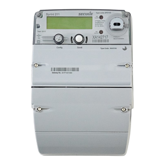
- Page 1 Sprint 211 electricity meter with Skyline- i 533/033 communication module Installation Manual BGX701-160-R01...
- Page 2 Secure Meters Ltd. Other product names are trademarks or registered trade names of their respective owners. As part of Secure Meter’s continuous endeavour to improve product design, specifications mentioned are liable to change. Page 2 of 48...
-
Page 3: Table Of Contents
Terms and abbreviations ........................7 Product overview and operating principle ................8 Product description ........................9 Sprint 211 main features ..........................9 Information printed on Sprint 211 front cover ....................11 Meter specifications ........................12 General specifications ..........................12 Firmware ..............................14 Handling, storage and operating conditions .................... - Page 4 Appendix 1: Fitting an external antenna ................. 41 Appendix 2: Replacing the communication module ............... 43 Appendix 3: Opening and fitting the secondary terminal cover ..........45 Notes ............................... 46 Notes ............................... 47 Page 4 of 48 Sprint 211 Installation Manual BGX701-160-R01...
-
Page 5: Important
Specifications / features listed in this document are the most advanced available with Secure Meters on the date of release of this document, and hence should not be considered as default. Availability of all or some of the same depends upon the product builds and may not be readily available. -
Page 6: Disclaimer
Disclaimer Secure Meters assume no responsibility for damage caused to the meter under the following circumstances: Irregular maintenance / improper installation Imprudence or carelessness during installation Normal (or abnormal) wear and tear of insulation Accidental contact with hazardous elements Immersion of meter in water... -
Page 7: Terms And Abbreviations
Sprint 211 Smart electricity meter with a display push buttons. Internal 3G module mounted inside the communication module cover of Skyline-i 533/033 Sprint 211 electricity meter. The manual refers to it as the communication module. Abbreviations and Acronyms Acronym Description... -
Page 8: Product Overview And Operating Principle
1 Product overview and operating principle Sprint 211 is a three phase, single element electricity meter that supports both Credit and Prepayment (or Pay As You Go (PAYG) modes of operation for Smart Metering. It is available in two variants one with load control feature and other without this feature. -
Page 9: Product Description
2 Product description This section describes the salient features of the product. 2.1 Sprint 211 main features BGX701-160-R01 Sprint 211 Installation Manual Page 9 of 48... - Page 10 2. Push Buttons - Two push buttons Left and Right, allow interactions with Sprint 211. These buttons are used for various user operations such as display navigation, boost operation etc.
-
Page 11: Information Printed On Sprint 211
16. Phase Selection Sockets – Either of phases i.e. A, B or C can be used to energise the auxiliary load connected to L1 with the help of a phase selection provision provided on Sprint 211’s terminal block. This is done by tightening the screw provided in any ONE of the phase selection sockets above each phase. -
Page 12: Meter Specifications
3 Meter specifications This section describes the mechanical, electrical, compliance, hardware and environmental specifications for the Sprint 211 meter. 3.1 General specifications S. No. Specification Description Mechanical Dimensions (mm) 221 (H) x 180 (W) x 116 (D) Weight 2.2 kg approx (Actual weight may vary with variants) - Page 13 Dielectric Strength AC voltage withstands as per BS EN 50470-1 • Impulse withstand as per BS EN 50470-1 BS EN 50470-1, 50470-3 Class B Compliance Metrology BS EN 50470-1, 50470-3 Power Consumption BGX701-160-R01 Sprint 211 Installation Manual Page 13 of 48...
-
Page 14: Firmware
Note: The current firmware name and version are available in meter readings and on the meter’s display. 3.3 Handling, storage and operating conditions The Sprint 211 meter is an electronic device containing delicate components, which should be handled carefully during transit, storage, and installation. The meter should be protected from physical vibration and shocks. -
Page 15: Standards And External Certification
Electrical requirements MID Approval 0120/SGS0337 3.5 Connection terminals The following diagram shows the internal connection for two build types of the Sprint 211. 3.5.1 Connection diagram, with disconnect and LC 3.5.2 Connection diagram, with disconnect and without LC BGX701-160-R01 Sprint 211 Installation Manual... -
Page 16: Installation And Mounting Details
4 Installation and mounting details The installation of Sprint 211 must be performed with extra care and attention. The existence of dangerous electrical voltage may be fatal. Hence, these operations should be performed only by skilled personnel. 4.1 Lifting the meter Meter should be handled with care while lifting and transferring from one place to another. - Page 17 Ensure safe working conditions near the installation location. Check whether the consumer installation can be isolated safely from the mains. Check for the polarity of the supply. Label the wiring for correct connections. BGX701-160-R01 Sprint 211 Installation Manual Page 17 of 48...
-
Page 18: Dimensions And Mounting Arrangements
This section displays the dimensions of the product in various views. The meter terminal dimensions are also provided here. Details such as possible vertical and horizontal mounting positions are included to ease the installation process. Page 18 of 48 Sprint 211 Installation Manual BGX701-160-R01... - Page 19 Figure 4: Terminal connections Sprint 211 supports various mounting options which include arrangements to substitute any currently installed meters too. The figure below displays the rear view fixing dimensions in mm. BGX701-160-R01 Sprint 211 Installation Manual Page 19 of 48...
- Page 20 Figure 5: Dimensions and Mounting Details All the possible mounting options are described in the table below: Table 2: Sprint 211 Mounting measurements Mounting Horizontal distance (mm) Options Vertical distance (mm) arrangement holes Option 1 1, 2, 3 Option 2...
-
Page 21: Pre-Installation Checklist
(or modem) is installed inside a metal enclosure. 4.6.3 Selecting suitable mounting screws Given below is a list of recommended Mounting Screws to ensure proper fixing of meter at the mounting location. BGX701-160-R01 Sprint 211 Installation Manual Page 21 of 48... -
Page 22: Selecting The Cable
Amperes) This is a general chart and the installer may refer to vendor specification for the accurate details. Copper cable is highly recommended for current ratings above 50 ampere. Page 22 of 48 Sprint 211 Installation Manual BGX701-160-R01... -
Page 23: Installation Procedure
Ensure that all the necessary tools are available. Refer to the section 4.6.1 for more details. By visual inspection, check for any loose or exposed electrical connections near the installation location. If required, secure the loose connections or use fast-drying, commercially available insulation coating cover exposed connections. -
Page 24: Preparing Cables For Termination
Ensure that a cable of the correct rating is being used. If a cable of lower rating is used, replace it with appropriate cable. Strip the insulation of cables used as per given recommendations. Following table shows the internal bore diameters of all the terminals. Table 5: Sprint 211 Internal Bore Diameters S. No Meter terminal type Internal bore... -
Page 25: Making Connections
Figure 7: Terminal Block showing all the Load Terminals For Load Control connections, do the following: Pull out the insulation cover provided for the phase selection sockets on the Sprint 211’s terminal block. (Refer Figure 10: Load Control Connections). By default, the selection socket LA is set to energise the auxiliary load connected to L1. - Page 26 If there is no load, the calibration LEDs should not flash. Seal the meter with the available sealing kit. Utility seals can be applied at terminal cover and Configuration button. The sealing provision in Sprint 211 is as follows: •...
-
Page 27: Display And Button Details
5 Display and button details Sprint 211 is equipped with a large multi-segment alpha-numeric LCD display and two buttons for the essential user interface. Figure 9: Segment Check for the LCD Display The LCD screen has various sections and annunciators for displaying specific bits of information such as supply or load connection status, parameter values, user messages etc. - Page 28 Load contactor annunciators - glowing of a particular LC annunciator indicates that the switch state is ON. The annunciator is turned off when the switch state is OFF. For Sprint 211, only auxiliary switch 1 is used. During the switch time randomisation period, auxiliary switch 1 flashes to indicate the connection status.
-
Page 29: Using The Display
To activate/de-activate Boost Auto mode Auto Mode is the default mode for Sprint 211 display. The configured parameters scroll automatically within a specified period. The auto cycle ends with a brief sleep mode of two minutes, following which the display cycle is repeated. - Page 30 Case 1: When the meter display is viewed from a level above the meter. Case 2: When the meter display is viewed from a level below the meter. Figure 10: LCD Viewing Angle Page 30 of 48 Sprint 211 Installation Manual BGX701-160-R01...
-
Page 31: Appendix 1: Commissioning
Step 1: Press left push button Press left push button continuously for 5 seconds on the electricity meter to activate the commissioning process. Note: “LC ON 1” display is only applicable for Sprint 211 Aux variant. Note: ‘Busy’ indicates the wait Note: An already comissioned... - Page 32 This display will appear if the Right push button is pressed in any of the previous steps showing phase displays. Next press the Right button to confirm selection Followed by Selected Phase display for E.G. Page 32 of 48 Sprint 211 Installation Manual BGX701-160-R01...
- Page 33 Switch type Test applicable for variants • 3P4W (with Auxiliary switch) Mains (Marked with * • 3P4W (without Auxiliary switch) below) Auxiliary (Marked 3P4W (with Auxiliary switch) with ** below) BGX701-160-R01 Sprint 211 Installation Manual Page 33 of 48...
- Page 34 Note: If the switch test (Mains or Aux) fails at any stage, the following display appears: On pressing any button, the commissioning process is terminated and the display returns to the default display sequence. Page 34 of 48 Sprint 211 Installation Manual BGX701-160-R01...
- Page 35 Note: If the meter is unable to communicate with communication module, the following display appears: On pressing any button, the commissioning process is terminated and the display returns to the default display sequence. BGX701-160-R01 Sprint 211 Installation Manual Page 35 of 48...
- Page 36 5 seconds of pressing the left another 30 seconds. The installer push button must wait until this period times out. Note: During this time, meter will not respond to any button press. Followed by Page 36 of 48 Sprint 211 Installation Manual BGX701-160-R01...
- Page 37 WAN status is received, it push button is pressed after automatically switches to next completion of the signal strength display without waiting for timeout. test. The meter performs WAN BGX701-160-R01 Sprint 211 Installation Manual Page 37 of 48...
-
Page 38: Without Wan' Scenario
HAN icon flashes when HAN pairing is enabled. Step 6: Installation confirmation Note: This display allows the installer to take a decision to go Press the left push button to Page 38 of 48 Sprint 211 Installation Manual BGX701-160-R01... -
Page 39: With Wan' Scenario
HAN antenna, make sure that it is Press the right push button on the physically connected. required display to select the HAN antenna and move to the next HAN Icon flashes when HAN display. pairing is enabled. BGX701-160-R01 Sprint 211 Installation Manual Page 39 of 48... - Page 40 The Install code is displayed for 4 tariff configured in the meter. minutes. The display returns to the default display sequence at the end of the timeout duration or if any buttton is pressed. Page 40 of 48 Sprint 211 Installation Manual BGX701-160-R01...
-
Page 41: Appendix 1: Fitting An External Antenna
Be careful when screwing the SMA connector. Do not use excessive force. Fit the cable into the cable clips on the module. The cable passes through the antenna slot on the edge of the communication module. BGX701-160-R01 Sprint 211 Installation Manual Page 41 of 48... - Page 42 (or modem) is installed inside a metal enclosure. Recommendations for external antenna to be used (WAN/HAN): Manufacturer: Panorama (Part number: LPW-BC3G-26-2SP) Any alternate antenna selection should be approved by Secure prior to installation to ensure compatibility and avoid degradation of communication performance. Antenna Placement Requirements...
-
Page 43: Appendix 2: Replacing The Communication Module
(on the communication module) and female connector (on the meter) fit smoothly. Ensure that the connector pins are not bent or damaged during insertion. A reference illustration is shown below. BGX701-160-R01 Sprint 211 Installation Manual Page 43 of 48... - Page 44 Secure the sealing screws by tightening appropriately. Page 44 of 48 Sprint 211 Installation Manual BGX701-160-R01...
-
Page 45: Appendix 3: Opening And Fitting The Secondary Terminal Cover
This will loosen the cover from the top. Refer to the figure below. Next pull the cover at the side walls in upward direction to dismantle completely. BGX701-160-R01 Sprint 211 Installation Manual Page 45 of 48... -
Page 46: Notes
Notes Page 46 of 48 Sprint 211 Installation Manual BGX701-160-R01... -
Page 47: Notes
Notes... - Page 48 +44 117 9788786 f: +44 117 9788701 Secure Controls (UK) Ltd South Bristol Business Park Roman Farm Road Bristol BS4 1UP United Kingdom p: +44 117 9788700 f: +44 117 9788701 Page 48 of 48 Sprint 211 Installation Manual BGX701-160-R01...
Need help?
Do you have a question about the Sprint 211 and is the answer not in the manual?
Questions and answers
How do I get a meter reading from a Secure Sprint 211 meter?