
Related Manuals for Secure Premier 211


Summary of Contents for Secure Premier 211
- Page 1 Premier 211 electricity meter with Skyline-i 543/033 communication module User Manual BGX701-075-R03 Page 1 of Premier 211 User Manual BGX701-075-R03...
- Page 2 Skyline-i 543/033 are registered trade names of Secure Meters Ltd. Other product names are trademarks or registered trade names of their respective owners. As part of Secure Meter’s continuous endeavour to improve product design, specifications mentioned are liable to change. BGX701-075-R03...
-
Page 3: Table Of Contents
Commonly used acronyms ......................8 Product overview and operating principle ................9 Product description ........................10 Premier 211 main features ......................... 10 Information printed on Premier 211 front cover ..................12 Premier 211 display and button details....................... 13 Using the display ............................14 2.4.1 Display types and viewing arrangements .................. - Page 4 Skyline-i 543/033 Rear View ......................41 Information on the communication module cover (Skyline-i 543/033) ............41 10-Pin interface connector details (Skyline-i 543/033) ................42 Appendix 1: LCD displays ......................43 Notes ..............................54 Notes ..............................55 BGX701-075-R03 Premier 211 User Manual Page 4 of 56...
-
Page 5: Important
Secure Meters undertake to correct such errors wherever possible, and request feedback from users in this regard. Secure Meters reserve the right to alter some or whole of the specifications mentioned in this document without any prior notice. For any queries or clarifications, the user is requested to email the Secure Meters’ support team at tech.support@securetogether.com.au... -
Page 6: Disclaimer
Disclaimer Secure Meters assume no responsibility for damage caused to the meter under the following circumstances: ● Irregular maintenance / improper installation ● Imprudence or carelessness during installation ● Normal (or abnormal) wear and tear of insulation ● Accidental contact with hazardous elements ●... -
Page 7: Precautions And Safety Practices
● Premier 211 is maintenance-free meter as it has no interchangeable or serviceable parts. To ensure a robust user experience, adhere to the environmental and technical specifications; and follow the instructions and safety measures to avoid risk of injury or damage to the equipment. For any further queries, you may contact the nearest sales representative. -
Page 8: Commonly Used Acronyms
Wide Area Network Head end system Identity Time Of Use Maximum demand Survey Integration Period Quality of Supply International Electro-technical Commission Input Output UTRN Unique transaction reference number UART Universal asynchronous receiver/ transmitter BGX701-075-R03 Premier 211 User Manual Page 8 of 56... -
Page 9: Product Overview And Operating Principle
Product overview and operating principle Premier 211 is a three phase, single element CT operated meter with fixed CT ratings. It supports credit mode of operation for Smart Metering. The meter supports 230V (+20%/– 20%) connection with the current of 5-20A. -
Page 10: Product Description
Product description This section describes the salient features of the product. 2.1 Premier 211 main features Page 10 of 56 Premier 211 User Manual BGX701-075-R03... - Page 11 14. Pulse Outputs – Two fixed pulse outputs, one for Active Import and other for Active Export. The outputs will be potential free. 15. A 2A Relay is provided in the Premier 211 meter which is used for managing load control applications. BGX701-075-R03...
-
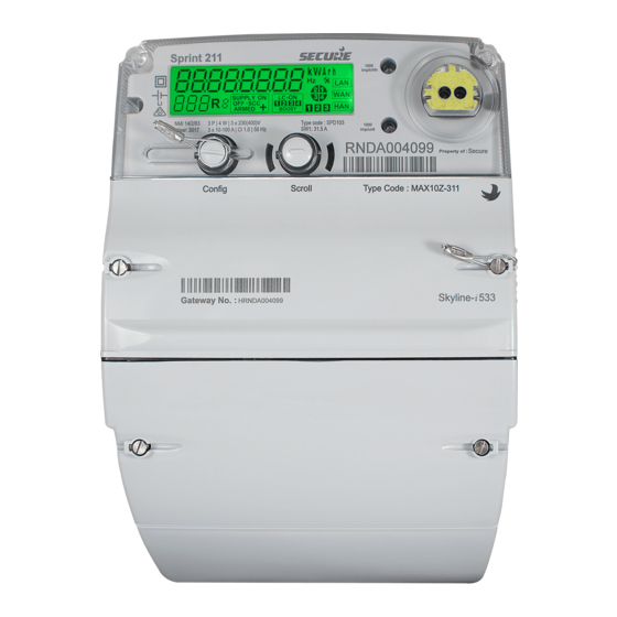
Page 12: Information Printed On Premier 211
Current rating Frequency control variant Figure 3: Information on the Premier 211 front cover *The Communication module information will be available on the front cover only for Premier 211 fitted with Skyline-i 543. Page 12 of 56 Premier 211 User Manual... -
Page 13: Premier 211 Display And Button Details
Premier 211 display and button details Premier 211 is equipped with a large multi-segment alpha-numeric LCD display and two buttons for the essential user interface. Figure 4: Segment Check for the LCD Display The LCD screen has various sections and annunciators for displaying specific bits of information such as relay or load connection status, parameter values, user messages etc. -
Page 14: Using The Display
S. No. Function Details Parameter Navigation Premier 211 may be configured to display a desired list of parameters. These parameters are logically grouped to appear as a different display page, each of which is assigned an individual display ID. Metrological LED... -
Page 15: Display Types And Viewing Arrangements
Selects the next parameter in the current page sequence Auto Mode Auto Mode is the default mode for Premier 211 display. The configured parameters scroll automatically within a specified period. The auto cycle ends with a brief sleep mode of two minutes, following which the display cycle is repeated. - Page 16 Case 1: When the meter display is viewed from a level above the meter. Case 2: When the meter display is viewed from a level below the meter. Figure 5: LCD Viewing Angle Page 16 of 56 Premier 211 User Manual BGX701-075-R03...
-
Page 17: Meter Specifications
Meter specifications This section describes the mechanical, electrical, compliance, hardware and environmental specifications for the Premier 211 meter. General specifications S. No. Specification Description Mechanical Dimensions (mm) 252 (H) x 180 (W) x 118 (D) without hook (with 35 mm extended main terminal cover) Weight 2.2 kg approx. - Page 18 2MB Flash, Data retention up to 15 years Type PVC, V-90, Copper Connecting Cables (Recommended -As per Size 4 mm (conductor diameter) service and installation for 20A practices) Voltage rating 600/1000V Page 18 of 56 Premier 211 User Manual BGX701-075-R03...
- Page 19 -10 °C to +60 °C as per NMI M6 Limit range of operation -20 °C to +70 °C Limit range for storage -25 °C to +70 °C Limit range for -25 °C to +70 °C BGX701-075-R03 Premier 211 User Manual Page 19 of 56...
-
Page 20: Firmware
Note: The current firmware name and version are available in meter readings and on the meter’s display. Handling, storage and operating conditions The Premier 211 meter is an electronic device containing delicate components, which should be handled carefully during transit, storage, and installation. The meter should be protected from physical vibration and shocks. -
Page 21: Standards And External Certification
Ideally the meter should be stored and operated in a dry, well ventilated, climate-controlled building. Rapid changes in temperature and humidity should be avoided. Standards and external certification The Premier 211 meter with internal communication module conforms to the following standards: Table 4: Standards Electrical requirements AS62052.11, AS62053.22, AS62053.23, NMI M6-1... -
Page 22: Functional Specifications
Functional specifications Premier 211 is configured with the Default or Credit mode as per the supplier’s request. The meter mode settings are downloaded when the meter becomes part of Smart Metering System and is connected to Head End System using WAN. -
Page 23: Registers, Load Profile And Snapshots
4.2.3 Maximum demand (MD) registers Premier 211 calculates Maximum Demand (MD) for Active Import and Active Export energies. The MD value in the MD register is updated whenever the average demand over the programmed Maximum Demand Integration Period (DIP) exceeds the currently stored MD value. The new MD value is recorded in the meter along with the date and time of its occurrence. -
Page 24: Load Profile
Standard (Primary) load profile Premier 211 can be configured to store 201 days of 5 minutes’ load profile data, 1212 days of half-hourly load profile data, 605 days of 15 minutes’ load profile data and 2423 days of hourly load profile data for each energy channel on a first-in-first-out (FIFO) roll over basis. -
Page 25: Energy Snapshot Logging
300 SIPs is performed in the meter. 4.2.5 Energy snapshot logging Premier 211 logs the following four types of snapshots: a) Midnight snapshot b) Billing snapshot... - Page 26 4.2.5.1 Midnight Snapshot Premier 211 takes a daily snapshot of the energy registers at each midnight and stores the data for the last 14 days. The snapshot data is updated daily on an FIFO basis. The meter does not record midnight snapshots for days when power was off for the complete day. For example, if the meter power was off at 11:45 PM on Monday and resumed at 10.00AM on Wednesday, the midnight...
-
Page 27: Metrology Leds
5000 impulse/kWh or kVArh. Time keeping The Premier 211 clock maintains time in hours, minutes, and seconds format. All data logging (e.g. load survey data, events data, maximum demands and snapshots) take place using the standard time whereas displayed date and time use local time (i.e. -
Page 28: Setting Time From The Hes
A Unique Transaction Reference Number (UTRN) is a code is required to modify existing configurations in the meter. A maximum of 100 UTRN events can be recorded by the meter (either accepted or rejected). There are three types of UTRNs: Page 28 of 56 Premier 211 User Manual BGX701-075-R03... -
Page 29: Meter Mode Switching
Meter mode switching Default operation mode Premier 211 can be switched to the default operation mode via the engineering service UTRN or on receipt of an authenticated command. Credit operation mode Premier 211 can be switched to the credit operation mode on receipt of an authenticated command only. -
Page 30: Tariff Configuration
14:00 – 20:00 TOU3 20:00 – 00:00 Premier 211 meters supports configuration of TOU tariff structure for 4 seasons, 4 weeks, 17 days, 48 switching points per day and 70 special dates. Page 30 of 56 Premier 211 User Manual... -
Page 31: Resetting Counters
Clears snapshot registers, historical load profile information, UTRN log, account log, hardware log, configuration log, supply quality log, operating condition log, supply log and tamper log. ● Changes the meter’s relay state to ‘Off’ or ‘ARMED’ state. BGX701-075-R03 Premier 211 User Manual Page 31 of 56... -
Page 32: Change Of Tenancy (Cot)
By default, relay is in OFF state and its state can be changed through remote command. Page 32 of 56 Premier 211 User Manual BGX701-075-R03... -
Page 33: Relay Action Sequence
Switches to ARMED state 4.10.2 Connecting/disconnecting relay remotely In Premier 211, the relay can be in ARMED, ON or OFF state remotely using the authenticated supply command (i.e. via UTRN) either immediately or on a scheduled date (in 30 minutes’ resolution). The scheduled date must be within 365 days (compile time configurable) from the current date. -
Page 34: Tamper Events
(based on P time) if the load detected is above a certain predefined threshold. 4.10.3 Tamper events Premier 211 can be configured to disconnect the relay when it detects a tamper event. Following tamper events are configured for supply disconnection: ●... -
Page 35: Pulse Output Functions
4.12 Detecting and logging events Premier 211 detects the following types of logs and can store a maximum of one hundred (100) events for each on a rolling first in first out (FIFO) basis in eight (8) separate groups: ●... -
Page 36: Hardware
4.12.3 Tamper Premier 211 can be configured to disconnect the supply when it detects a tamper event and send alerts for such events to the HES. The meter is programmed to record the following as tamper events together with the date and time of their occurrence: ●... -
Page 37: Utrn
Switching to Credit modes ● Profile and event configuration ● Time setting (WSE and communication module) ● Cancellation of delayed meter configuration ● Configuration, enabling or disabling of DST ● Setting the Site ID BGX701-075-R03 Premier 211 User Manual Page 37 of 56... -
Page 38: Communication Channels
4.13 Communication channels Premier 211 with the Skyline-i 033/543 communication module has the following communication channels: ● ANSI optical port - this port, fitted on the meter is designated as Port-1 and is used to communicate with the meter locally. -
Page 39: Engineering Services
Device information having meter serial number, manufacturing serial number, firmware identity information, device temperature and so on. ● Supplier tariff information ● Meter operation data as cumulative energy registers, instantaneous electrical parameters (voltage, current and power factor, power frequency), and counters. BGX701-075-R03 Premier 211 User Manual Page 39 of 56... -
Page 40: Communication Module (Skyline-I 033/Skyline-I 543)
Communication module (Skyline- 033/Skyline-i 543) Premier 211 is supplied with Skyline-i 033 (without Zigbee module and 3G support) and Skyline-i 543 (with Zigbee module and 4G support). 5.1 Overview of Skyline-i 033 and Skyline-i 543 The communication module is fitted inside the meter’s communication module and serves as the communication gateway to the Head End System (HES) via a Wide Area Network (WAN) and other smart metering devices via a Home Area Network (HAN). -
Page 41: Skyline-I 543/033 Rear View
Module serial number Figure 7: Skyline-i 033 front cover printings Gateway serial number Barcode for gateway serial Communication number module Gateway category code Figure 8: Skyline-i 543 front cover printings BGX701-075-R03 Premier 211 User Manual Page 41 of 56... -
Page 42: 10-Pin Interface Connector Details (Skyline-I 543/033)
3.3 V 3.3 V from the communication module Receive signal from the meter micro controller. Transmit signal to the meter micro controller. Table 8: Functions of communication module interface connector PINs Page 42 of 56 Premier 211 User Manual BGX701-075-R03... -
Page 43: Appendix 1: Lcd Displays
Appendix 1: LCD displays S.No Description Premier 211 PAYG Credit Default Page 0 (Configurable Display Page - Identifier displayed as configured at mfg.) Meter Local Time Meter Local date Net Active Import Net Active Export Net Reactive Import Net Reactive Export... - Page 44 Meter status: Battery failure all status flags are set Tariff Name "8" characters only Page 1 (Cumulative Energy Values and High Resolution) Page number of the current displayed page Test all segments ON Page 44 of 56 Premier 211 User Manual BGX701-075-R03...
- Page 45 Element 1 Reactive Export Element 2 Active Import Element 2 Active Export Element 2 Reactive Import Element 2 Reactive Export Element 3 Active Import Element 3 Active Export Element 3 Reactive Import BGX701-075-R03 Premier 211 User Manual Page 45 of 56...
- Page 46 Net Element 2 Active Import (Accessed from grid) Page 2 Diagnostic Data Display Page number of the current displayed page Meter serial number- lower order Meter serial number- higher order Page 46 of 56 Premier 211 User Manual BGX701-075-R03...
- Page 47 Meter status: Clock invalid Meter status: Low battery Meter status: Battery failure all status flags are set Battery hours (displayed value in hours will be rolled over after 999999) "HAN closed" BGX701-075-R03 Premier 211 User Manual Page 47 of 56...
- Page 48 "No network" or "HAN module not supported" "Permit joining ON" "No communication with HUB" "IDLE" "Attempt going on" "Connected" "No Power" "No communication with HUB" No signal Signal strength in dB Install code Page 48 of 56 Premier 211 User Manual BGX701-075-R03...
- Page 49 Page number of the current displayed page Frequency Scaling of the metrological LED-1 Scaling of the metrological LED-2 Voltage Phase 1 Voltage Phase 2 Voltage Phase 3 Active Current Phase 1 BGX701-075-R03 Premier 211 User Manual Page 49 of 56...
- Page 50 Line Current Phase 2 Line Current Phase 3 Active Power Phase 1 Active Power Phase 2 Active Power Phase 3 Power Factor Phase 1 Power Factor Phase 2 Power Factor Phase 3 Page 50 of 56 Premier 211 User Manual BGX701-075-R03...
- Page 51 Identifier (IP) represents Import and (2) represents element Standing Charge Per Day "c" represents cents Active Import Rate register. "A01" represents Active Import rate register Meter only displays configured registers. BGX701-075-R03 Premier 211 User Manual Page 51 of 56...
- Page 52 This is for cost of consumption & generation since last billing. (Header) This is for cost of consumption since last billing. (Value) This is for cost of generation since last billing. (Value) Page 52 of 56 Premier 211 User Manual BGX701-075-R03...
- Page 53 Further, press left button to connect. Press right button to confirm. Load Limit Display High Load (90% of over load threshold) Over Load BAD Display Bad display (Identifier displayed as config.) BGX701-075-R03 Premier 211 User Manual Page 53 of 56...
-
Page 54: Notes
Notes Page 54 of 56 Premier 211 User Manual BGX701-075-R03... -
Page 55: Notes
Notes BGX701-075-R03 Premier 211 User Manual Page 55 of 56... - Page 56 United Kingdom p: + 91 294 2492300 p: +44 1962 840048 f: +91 294 2492310 f: +44 1962 841046 Secure Meters (Australia) Pty. Ltd Advanced Energy Monitoring Systems Ltd 258 Darebin Road South Bristol Business Park Fairfield VIC 3078 Roman Farm Road...
Need help?
Do you have a question about the Premier 211 and is the answer not in the manual?
Questions and answers