
Subscribe to Our Youtube Channel
Related Manuals for ASROCK Z690D4U/G5


Summary of Contents for ASROCK Z690D4U/G5
- Page 1 User Manual Z690D4U/G5 Z690D4U-2L2T/G5 W680D4U-2L2T/G5 Z690D4U-2L2T/G5/BCM W680D4U-2L2T/G5/BCM Version 1.0 Published December 2023 Copyright©2023 ASRock Rack INC. All rights reserved.
- Page 2 (including damages for loss of profits, loss of business, loss of data, interruption of business and the like), even if ASRock Rack has been advised of the possibility of such damages arising from any defect or error in the documentation or product.
- Page 3 - Reorient or relocate the receiving antenna. - Increase the separation between the equipment and receiver. - Connect the equipment into an outlet on a circuit different from that to which the receiver is connected. - Consult the dealer or an experienced radio/TV technician for help. INTEL END USER SOFTWARE LICENSE AGREEMENT IMPORTANT - READ BEFORE COPYING, INSTALLING OR USING.
- Page 4 Licensee’s intellectual property rights, to incorporate or otherwise utilize those comments and suggestions. TERMINATION OF THIS LICENSE. Intel or the sublicensor may terminate this license at any time if Licensee is in breach of any of its terms or conditions. Upon termination, Li- censee will immediately destroy or return to Intel all copies of the Software.
- Page 5 ASRock Rack follows the green design concept to design and manufacture our products, and makes sure that each stage of the product life cycle of ASRock Rack product is in line with global environmental regulations. In addition, ASRock Rack disclose the relevant information based on regulation requirements.
-
Page 6: Table Of Contents
Contents Chapter 1 Introduction Package Contents Specifications Unique Features Motherboard Layout Onboard LED Indicators I/O Panel Block Diagram Chapter 2 Installation Screw Holes Pre-installation Precautions Installing the CPU Installing the CPU Fan and Heatsink Installing Memory Modules (DIMM) Expansion Slots (PCI Express Slots) Jumper Setup Onboard Headers and Connectors Dr. - Page 7 3.1.1 UEFI Menu Bar 3.1.2 Navigation Keys Main Screen OC Tweaker 3.3.1 CPU Configuration 3.3.2 DRAM Configuration 3.3.3 Voltage Configuration Advanced Screen 3.4.1 CPU Configuration 3.4.2 Storage Configuration 3.4.3 PCH-FW Configuration 3.4.4 Storage Configuration 3.4.5 NVME Configuration 3.4.6 ACPI Configuration 3.4.7 USB Configuration 3.4.8 Super IO Configuration 3.4.9 Serial Port Console Redirection...
- Page 8 Security Screen 3.5.1 Key Management Boot Screen Server Mgmt 3.7.1 System Event Log 3.7.2 BMC Network Configuration 3.7.3 BMC Tools Event Logs Exit Screen Chapter 4 Software Support Download and Install Operating System Download and Install Software Drivers Contact Information Chapter 5 Troubleshooting Troubleshooting Procedures Technical Support Procedures...
-
Page 9: Chapter 1 Introduction
In case any modifications of this manual occur, the updated version will be available on ASRock Rack website without further notice. You may find the latest memory and CPU support lists on ASRock Rack website as well. ASRock Rack’s Website: www.ASRockRack.com If you require technical support related to this motherboard, please visit our website for specific information about the model you are using. -
Page 10: Specifications
1.2 Specifications Z690D4U-2L2T/G5 / W680D4U-2L2T/G5 / Z690D4U-2L2T/G5/BCM / W680D4U-2L2T/G5/BCM MB Physical Status Form Factor Micro-ATX Dimension 9.6'' x 9.6'' (244 mm x 244 mm) Processor System Z690D4U-2L2T/G5 / Z690D4U-2L2T/G5/BCM: - Supports 12 & 13 Gen Intel® Core™, Pentium® and Celeron® series processors W680D4U-2L2T/G5 / W680D4U-2L2T/G5/BCM: - Supports 12... - Page 11 Z690D4U & W680D4U G5 Series OCuLink 1 OCuLink (PCIe4.0 x4)* [CPU] 1 OCuLink (PCIe4.0 x4 or 4 SATA 6Gb/s) [PCH] 1 OCuLink (PCIe4.0 x4) [PCH] 1 OCuLink (PCIe3.0 x4) [PCH] Note *SLOT7 share lanes with OCuLink4. OCuLink4 will disable when SLOT7 is populated SATA/SAS Storage Intel®...
- Page 12 BIOS type AMI 256Mb SPI Flash ROM Features Plug and Play, ACPI 6.4 and above compliance wake up events, SMBIOS 2.8 and above, ASRock Rack Instant Flash Internal Connectors/Headers PSU connector 1 (24-pin, ATX main power), 2 (8-pin, ATX 12V)
- Page 13 Z690D4U & W680D4U G5 Series Enviroment Operating 10 - 35°C (50 - 95 degF) temperature Non-operating -40 - 70°C (-40 - 158degF) temperature This motherboard supports Wake from on Board LAN. To use this function, please make sure that the “Wake on Magic Packet from power off state” is enabled in Device Manager >...
- Page 14 Z690D4U/G5 MB Physical Status Form Factor Micro-ATX Dimension 9.6'' x 9.6'' (244 mm x 244 mm) Processor System Supports 12 Gen Intel® Core™, Pentium® and Celeron® series processors Socket Single Socket LGA 1700 Thermal Design 125W Power (TDP) Chipset Intel® Z690...
- Page 15 IPMI Dedicated 1 RJ45 Dedicated IPMI LAN port by Realtek RTL8211F GLAN System BIOS BIOS type AMI 256Mb SPI Flash ROM Features Plug and Play, ACPI 6.4 and above compliance wake up events, SMBIOS 2.8 and above, ASRock Rack Instant Flash...
- Page 16 Internal Connectors/Headers PSU connector 1 (24-pin, ATX main power), 2 (8-pin, ATX 12V) Auxiliary panel 1 (18-pin): chassis intrusion, system fault LED, LAN1/LAN2 header activity LED, locate, SMBus System panel 1 (9-pin): power switch, reset switch, system power LED, header HDD activity LED NMI button VGA header...
-
Page 17: Unique Features
. With this utility, you can press the <F6> key during the POST or the <F2> key to enter into the BIOS setup menu to access ASRock Rack Instant Flash. Just launch this tool and save the new BIOS file to your USB flash drive, floppy disk or hard drive, then you can update your BIOS only in a few clicks without preparing an additional floppy diskette or other complicated flash utility. -
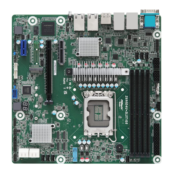
Page 18: Motherboard Layout
1.4 Motherboard Layout Z690D4U-2L2T/G5 / W680D4U-2L2T/G5 / Z690D4U-2L2T/G5/BCM / W680D4U-2L2T/G5/BCM 24.4cm (9.6 in) AT XPWR1 BA T1 PSU_SMB 1 F RNT_VGA 1 PWM_CFG1 AT X 12V 2 AT X 12V 1 DDR3_B 1 (6 4 bit , 2 40-pin module ) DDR5_B 2 (6 4 bit , 2 88-pin module ) F AN7 DDR3_A1 (6 4 bit , 2 40-pin module ) - Page 19 Z690D4U & W680D4U G5 Series Description Front VGA Header (FRNT_VGA1) PWM Configuration Header (PWM_CFG1) 2 x 288-pin DDR5 DIMM Slots (DDR5_A1, DDR5_B1) ATX 12V Power Connector (ATX12V1) ATX 12V Power Connector (ATX12V2) PSU SMBus Header (PSU_SMB1) ATX Power Connector (ATXPWR1) 2 x 288-pin DDR5 DIMM Slots (DDR5_A2, DDR5_B2) Chassis Fan Connector (FAN4) Chassis Speaker Header (SPEAKER1)
- Page 20 Description Chassis Fan Connector (FAN5) Chassis Fan Connector (FAN6) Chassis Fan Connector (FAN7)
- Page 21 Z690D4U & W680D4U G5 Series Z690D4U/G5 24.4cm (9.6 in) AT XPWR1 BA T1 F RNT_VGA 1 PSU_SMB 1 PWM_CFG1 AT X 12V 2 AT X 12V 1 DDR3_B 1 (6 4 bit , 2 40-pin module ) DDR5_B 2 (6 4 bit , 2 88-pin module )
- Page 22 Description Front VGA Header (FRNT_VGA1) PWM Configuration Header (PWM_CFG1) 2 x 288-pin DDR5 DIMM Slots (DDR5_A1, DDR5_B1) ATX 12V Power Connector (ATX12V1) ATX 12V Power Connector (ATX12V2) PSU SMBus Header (PSU_SMB1) ATX Power Connector (ATXPWR1) 2 x 288-pin DDR5 DIMM Slots (DDR5_A2, DDR5_B2) Chassis Fan Connector (FAN4) Chassis Speaker Header (SPEAKER1) USB 3.2 Gen1 Header (USB3_3_4)
- Page 23 Z690D4U & W680D4U G5 Series Description Chassis Fan Connector (FAN6) Chassis Fan Connector (FAN7)
-
Page 24: Onboard Led Indicators
1.5 Onboard LED Indicators DDR3_B1 (64 bit, 240-pin module) DDR3_A1 (64 bit, 240-pin module) DDR3_B1 (64 bit, 240-pin module) DDR3_A1 (64 bit, 240-pin module) Z690D4U-2L2T/G5 W680D4U-2L2T/G5... - Page 25 Z690D4U & W680D4U G5 Series Item Status Description FAN5_LED1 FAN5 failed FAN6_LED1 FAN6 failed FAN7_LED1 FAN7 failed SB_PWR1 Green STB PWR ready FAN4_LED1 FAN4 failed FAN3_LED1 FAN3 failed FAN2_LED1 FAN2 failed FAN1_LED1 FAN1 failed BMC_LED1 Green BMC heartbeat LED...
-
Page 26: I/O Panel
10G LAN RJ-45 Port (LAN3)** LAN RJ-45 Port (IPMI_LAN)* 10G LAN RJ-45 Port (LAN4)** 1G LAN RJ-45 Port (LAN1)*** UID Switch (UID1) 1G LAN RJ-45 Port (LAN2)*** Z690D4U/G5 No. Description No. Description VGA Port (VGA1) 1G LAN RJ-45 Port (LAN2)*** Serial Port (COM1) HDMI Port (2.0b) - Page 27 Z690D4U & W680D4U G5 Series LAN Port LED Indications *There are two LED next to the LAN port. Please refer to the table below for the LAN port LED indications. ACT/LINK LED SPEED LED LAN Port Dedicated IPMI LAN Port LED Indications Activity / Link LED Speed LED Status...
- Page 28 ***There are two LEDs on each LAN port. Please refer to the table below for the LAN port LED indications. ACT/LINK LED SPEED LED LAN Port 1G LAN Port LED Indications Activity / Link LED Speed LED Status Description Status Description No Link 10Mbps connection or...
-
Page 29: Block Diagram
Z690D4U & W680D4U G5 Series 1.7 Block Diagram Z690D4U/G5 / Z690D4U-2L2T/G5 / W680D4U-2L2T/G5 Z690D4U-2L2T/G5 / W680D4U-2L2T/G5 topology DDR5 [ECC/non-ECC] DDR5 [ECC/non-ECC] 4400MT/s (2DPC-1DIMM) PCI-E X16 4000MT/s (2DPC-2DIMM 1R) SLOT6 3600MT/s (2DPC-2DIMM 2R) DDR5 [ECC/non-ECC] INTEL DDR5 [ECC/non-ECC] PCI-E X4 Alder Lake-S CPU... - Page 30 Z690D4U-2L2T/G5/BCM / W680D4U-2L2T/G5/BCM Z690D4U-2L2T/G5/BCM / W680D4U-2L2T/G5/BCM topology DDR5 [ECC/non-ECC] DDR5 [ECC/non-ECC] 4400MT/s (2DPC-1DIMM) PCI-E X16 4000MT/s (2DPC-2DIMM 1R) SLOT6 3600MT/s (2DPC-2DIMM 2R) DDR5 [ECC/non-ECC] INTEL DDR5 [ECC/non-ECC] PCI-E X4 Alder Lake-S CPU Switch PCIE x4 Gen4 SLOT7 HDMI LGA-1700 Pin Socket OCuLink4 (PCI-Ex4) DisplayPort...
-
Page 31: Chapter 2 Installation
Z690D4U & W680D4U G5 Series Chapter 2 Installation This is a mATX form factor (9.6'' x 9.6'', 24.4 cm x 24.4 cm) motherboard. Before you install the motherboard, study the configuration of your chassis to ensure that the motherboard fits into it. Make sure to unplug the power cord before installing or removing the motherboard. -
Page 32: Installing The Cpu
2.3 Installing the CPU 1. Before you insert the 1700-Pin CPU into the socket, please check if the PnP cap is on the socket, if the CPU surface is unclean, or if there are any bent pins in the socket. Do not force to insert the CPU into the socket if above situation is found. Otherwise, the CPU will be seriously damaged. - Page 33 Z690D4U & W680D4U G5 Series Please save and replace the cover if the processor is removed. The cover must be placed if you wish to return the motherboard for after service.
-
Page 34: Installing The Cpu Fan And Heatsink
2.4 Installing the CPU Fan and Heatsink... -
Page 35: Installing Memory Modules (Dimm)
Z690D4U & W680D4U G5 Series 2.5 Installing Memory Modules (DIMM) This motherboard provides four 288-pin DDR5 (Double Data Rate 5) DIMM slots, and supports Dual Channel Memory Technology. 1. For dual channel configuration, you always need to install identical (the same brand, speed, size and chip-type) DDR5 DIMM pairs. - Page 36 The DIMM only fits in one correct orientation. It will cause permanent damage to the motherboard and the DIMM if you force the DIMM into the slot at incorrect orientation.
-
Page 37: Expansion Slots (Pci Express Slots)
Z690D4U & W680D4U G5 Series 2.6 Expansion Slots (PCI Express Slots) There are 4 PCI Express slots on this motherboard. PCIE slot: PCIE4 (PCIe 3.0 x1 slot) is used for PCI Express x1 lane width cards. PCIE6 (PCIe 5.0 x16 slot) is used for PCI Express x16 lane width cards. PCIE7 (PCIe 4.0 x4 slot) is used for PCI Express x4 lane width cards. -
Page 38: Jumper Setup
2.7 Jumper Setup The illustration shows how jumpers are setup. When the jumper cap is placed on the pins, the jumper is “Short”. If no jumper cap is placed on the pins, the jumper is “Open”. The illustration shows a 3-pin jumper whose pin1 and pin2 are “Short” when a jumper cap is placed on these 2 pins. -
Page 39: Onboard Headers And Connectors
Z690D4U & W680D4U G5 Series 2.8 Onboard Headers and Connectors Onboard headers and connectors are NOT jumpers. Do NOT place jumper caps over these headers and connectors. Placing jumper caps over the headers and connectors will cause permanent damage to the motherboard. System Panel Header Connect the power switch, PLED+... - Page 40 Auxiliary Panel Header This header supports multiple (18-pin AUX PANEL1) functions on the front panel, including the front panel SMB, internet status indicator and chassis intrusion pin. A. Front panel SMBus connecting pin (6-1 pin FPSMB) This header allows you to connect SMBus (System Management Bus) equipment. It can be used for communication between peripheral equipment in the system, which has slower transmission rates, and power management equipment.
- Page 41 Z690D4U & W680D4U G5 Series Serial ATA3 Connectors These SATA3 connectors Right Angle: support SATA data cables for (SATA_4) (Lower) internal storage devices with (SATA_5) (Upper) up to 6.0 Gb/s data transfer (SATA_6) (Lower) rate. (SATA_7) (Upper) USB_PWR USB 2.0 Header There is one USB 2.0 header (9-pin USB_1_2) on this motherboard.
- Page 42 ATX 12V Power This motherboard provides Connectors two 8-pin ATX 12V power (8-pin ATX12V1) connectors. (8-pin ATX12V2) SPI_DQ3 SPI TPM Header This connector supports SPI SPI_PWR Dummy (13-pin TPM_BIOS_PH1) Trusted Platform Module SPI_MOSI RST# (TPM) system, which can TPM_PIRQ securely store keys, digital certificates, passwords, and SPI_TPM_CS# data.
- Page 43 Z690D4U & W680D4U G5 Series Intelligent Platform This 4-pin connector is No connect Management Bus Header used to provide a cabled (4-pin IPMB_1) base-board or front panel connection for value added IPMB_SCL IPMB_SDA features and 3rd-party add- in cards, such as Emergency Management cards, that provide management features using the IPMB.
- Page 44 IntA_PA_D+ IntA_PA_D- USB 3.2 Gen1 Header Besides two default USB 3.2 IntA_PA_SSTX+ IntA_PA_SSTX- (19-pin USB3_3_4) Gen1 ports on the I/O panel, IntA_PA_SSRX+ there is one USB 3.2 Gen1 IntA_PA_SSRX- Vbus header on this motherboard. This USB 3.2 Gen1 header can support two USB 3.2 Gen1 Vbus ports.
-
Page 45: Dr. Debug
Z690D4U & W680D4U G5 Series 2.9 Dr. Debug Dr. Debug is used to provide code information, which makes troubleshooting even easier. Please see the diagrams below for reading the Dr. Debug codes. Code Description 0x10 PEI_CORE_STARTED 0x11 PEI_CAR_CPU_INIT 0x15 PEI_CAR_NB_INIT 0x19 PEI_CAR_SB_INIT 0x31... - Page 46 0x63 DXE_CPU_INIT 0x68 DXE_NB_HB_INIT 0x69 DXE_NB_INIT 0x6A DXE_NB_SMM_INIT 0x70 DXE_SB_INIT 0x71 DXE_SB_SMM_INIT 0x72 DXE_SB_DEVICES_INIT 0x78 DXE_ACPI_INIT 0x79 DXE_CSM_INIT 0x90 DXE_BDS_STARTED 0x91 DXE_BDS_CONNECT_DRIVERS 0x92 DXE_PCI_BUS_BEGIN 0x93 DXE_PCI_BUS_HPC_INIT 0x94 DXE_PCI_BUS_ENUM 0x95 DXE_PCI_BUS_REQUEST_RESOURCES 0x96 DXE_PCI_BUS_ASSIGN_RESOURCES 0x97 DXE_CON_OUT_CONNECT 0x98 DXE_CON_IN_CONNECT...
- Page 47 Z690D4U & W680D4U G5 Series 0x99 DXE_SIO_INIT 0x9A DXE_USB_BEGIN 0x9B DXE_USB_RESET 0x9C DXE_USB_DETECT 0x9D DXE_USB_ENABLE 0xA0 DXE_IDE_BEGIN 0xA1 DXE_IDE_RESET 0xA2 DXE_IDE_DETECT 0xA3 DXE_IDE_ENABLE 0xA4 DXE_SCSI_BEGIN 0xA5 DXE_SCSI_RESET 0xA6 DXE_SCSI_DETECT 0xA7 DXE_SCSI_ENABLE 0xA8 DXE_SETUP_VERIFYING_PASSWORD 0xA9 DXE_SETUP_START 0xAB DXE_SETUP_INPUT_WAIT 0xAD DXE_READY_TO_BOOT 0xAE DXE_LEGACY_BOOT...
- Page 48 0xAF DXE_EXIT_BOOT_SERVICES 0xB0 RT_SET_VIRTUAL_ADDRESS_MAP_BEGIN 0xB1 RT_SET_VIRTUAL_ADDRESS_MAP_END 0xB2 DXE_LEGACY_OPROM_INIT 0xB3 DXE_RESET_SYSTEM 0xB4 DXE_USB_HOTPLUG 0xB5 DXE_PCI_BUS_HOTPLUG 0xB6 DXE_NVRAM_CLEANUP 0xB7 DXE_CONFIGURATION_RESET 0xF0 PEI_RECOVERY_AUTO 0xF1 PEI_RECOVERY_USER 0xF2 PEI_RECOVERY_STARTED 0xF3 PEI_RECOVERY_CAPSULE_FOUND 0xF4 PEI_RECOVERY_CAPSULE_LOADED 0xE0 PEI_S3_STARTED 0xE1 PEI_S3_BOOT_SCRIPT 0xE2 PEI_S3_VIDEO_REPOST...
- Page 49 Z690D4U & W680D4U G5 Series 0xE3 PEI_S3_OS_WAKE 0x50 PEI_MEMORY_INVALID_TYPE 0x53 PEI_MEMORY_NOT_DETECTED 0x55 PEI_MEMORY_NOT_INSTALLED 0x57 PEI_CPU_MISMATCH 0x58 PEI_CPU_SELF_TEST_FAILED 0x59 PEI_CPU_NO_MICROCODE 0x5A PEI_CPU_ERROR 0x5B PEI_RESET_NOT_AVAILABLE 0xD0 DXE_CPU_ERROR 0xD1 DXE_NB_ERROR 0xD2 DXE_SB_ERROR 0xD3 DXE_ARCH_PROTOCOL_NOT_AVAILABLE 0xD4 DXE_PCI_BUS_OUT_OF_RESOURCES 0xD5 DXE_LEGACY_OPROM_NO_SPACE 0xD6 DXE_NO_CON_OUT 0xD7 DXE_NO_CON_IN...
- Page 50 0xD8 DXE_INVALID_PASSWORD 0xD9 DXE_BOOT_OPTION_LOAD_ERROR 0xDA DXE_BOOT_OPTION_FAILED 0xDB DXE_FLASH_UPDATE_FAILED 0xDC DXE_RESET_NOT_AVAILABLE 0xE8 PEI_MEMORY_S3_RESUME_FAILED 0xE9 PEI_S3_RESUME_PPI_NOT_FOUND 0xEA PEI_S3_BOOT_SCRIPT_ERROR 0xEB PEI_S3_OS_WAKE_ERROR...
-
Page 51: Unit Identification Purpose Led/Switch
Z690D4U & W680D4U G5 Series 2.10 Unit Identification purpose LED/Switch With the UID button, You are able to locate the server you’re working on from behind a rack of servers. Unit Identification When the UID button on the purpose LED/Switch front or rear panel is pressed, (UID) the front/rear UID blue LED... -
Page 52: Dua Lan And Teaming Operation Guide
2.11 Dua LAN and Teaming Operation Guide Dual LAN with Teaming enabled on this motherboard allows two single connections to act as one single connection(s) for twice the transmission bandwidth, making data transmission more effective and improving the quality of transmission of distant images. Fault tolerance on the dual LAN network prevents network downtime by transferring the workload from a failed port to a working port. -
Page 53: Ssd Module Installation Guide (M2_1)
Z690D4U & W680D4U G5 Series 2.12 M.2 SSD Module Installation Guide (M2_1) The Ultra M.2 Socket (M2_1, Key M) supports type 2230/2242/2260/2280 M.2 PCI Express module up to Gen3 x4 (32GT/s) [PCH]. Installing the M.2 SSD Module Step 1 Prepare a M.2 SSD module and the screw. - Page 54 Step 3 Move the standoff based on the module type and length. The standoff is placed at the nut location D by default. Skip Step 3 and 4 and go straight to Step 5 if you are going to use the default nut. Otherwise, release the standoff by hand.
-
Page 55: Chapter 3 Uefi Setup Utility
Z690D4U & W680D4U G5 Series Chapter 3 UEFI Setup Utility 3.1 Introduction This section explains how to use the UEFI SETUP UTILITY to configure your system. The UEFI chip on the motherboard stores the UEFI SETUP UTILITY. You may run the UEFI SETUP UTILITY when you start up the computer. -
Page 56: Navigation Keys
3.1.2 Navigation Keys Please check the following table for the function description of each navigation key. Navigation Key(s) Function Description Moves cursor left or right to select Screens Moves cursor up or down to select items + / - To change option for the selected items <Tab>... -
Page 57: Main Screen
Z690D4U & W680D4U G5 Series 3.2 Main Screen Once you enter the UEFI SETUP UTILITY, the Main screen will appear and display the system overview. The Main screen provides system overview information and allows you to set the system time and date. Mother Board Information Enter this item to view the motherboard information. -
Page 58: Oc Tweaker
3.3 OC Tweaker CPU Vcore Compensation This option will make cpu to run at higher vcores as default. Please try to adjust this option when your cpu is not stable at default setting. Higher level will provide higher vcore. Save User Default Type a profile name and press enter to save your settings as user default. -
Page 59: Cpu Configuration
Z690D4U & W680D4U G5 Series 3.3.1 CPU Configuration CPU Turbo Ratio Information The CPU speed is determined by the CPU P-Core Ratio multiplied with the BCLK. Increasing the CPU P-Core Ratio will increase the internal CPU clock speed without affeceting the clock speed of other components. CPU P-Core Ratio The CPU speed is determined by the CPU P-Core Ratio multiplied with the BCLK. - Page 60 CPU Cache Ratio The CPU Internal Bus Speed Ratio. The maximum should be the same as the CPU Ratio. GT Frequency Conigure the frequency of the integrated GPU in MHz. CPU Flex Ratio Override Enable/Disable CPU Flex Ratio Programming. Flex Ratio can lower maximum non-turbo, especially for CPU wihout turbo function.
- Page 61 Z690D4U & W680D4U G5 Series Ring to Core Ratio Offset Disable Ring to Core Ratio Offset so the ring and core can run at the same frequency. SA PLL Frequency Override Configure SA PLL Frequency. BCLK TSC HW Fixup BCLK TSC HW Fixup disable during TSC copy from PMA to APIC. FLL Overclocking Mode Nominal is good for normal core ratio overclocking.
- Page 62 Intel Thermal Velocity Boost Voltage Optimizations This service controls thermal based voltage optimizations for processors that implment the Intel Thermal Velocity Boost (TVB) feature. TVB Information Enter this item to view TVB information. CPU Tj Max Set CPU Tj Max to adjust TCC Target Temperature. Support TjMax in the range of 62 to 115 deg Celsius.
- Page 63 Z690D4U & W680D4U G5 Series CPU Core Current Limit Configure the Voltage Regulator Current Limit. This value represents the Maximum instaneous current allowed at any given time. GT Unlimited Current Limit To unlock voltage regulator current limit completely, you can set this option to Enabled. GT Current Limit Configure the Voltage Regulator Current Limit.
-
Page 64: Dram Configuration
3.3.2 DRAM Configuration Memory Information Allows users to browse the serial presence detect (SPD) and Intel extreme memory profile (XMP) for DDR modules. DRAM Timing Configuration Load XMP Setting Load X MP settings to overclock the DDR memor y and perform beyond standard specications. - Page 65 Z690D4U & W680D4U G5 Series BCLK Frequency The CPU speed is determined by the CPU Ratio multiplied with the BCLK. Increasing the BCLK will increase the internal CPU clock speed but also affect the clock speed of other components. Primary Timing CAS# Latency (tCL) The time between sending a column address to the memory and the beginning of the data in response.
- Page 66 Refresh Cycle Time per Bank (tRFCpb) The number of clocks that a per back Refresh command takes to complete. RAS to RAS Delay (tRRD_L) The number of clocks between two rows activated in different banks of the same rank. RAS to RAS Delay (tRRD_S) The number of clocks between two rows activated in different banks of the same rank.
- Page 67 Z690D4U & W680D4U G5 Series Turn Around Timing Turn Around Timing Optimization Auto is enabled in general case. TAT Training Value tRDRD_sg Configure between module read to read delay. tRDRD_dg Configure between module read to read delay. tRDRD_dr Configure between module read to read delay. tRDRD_dd Configure between module read to read delay.
- Page 68 tWRRD_dr Configure between module write to read delay. tWRRD_dd Configure between module write to read delay. tWRWR_sg Configure between module write to write delay. tWRWR_dg Configure between module write to write delay. tWRWR_dr Configure between module write to write delay. tWRWR_dd Configure between module write to write delay.
- Page 69 Z690D4U & W680D4U G5 Series tRDWR_dr Configure between module write to read delay. tRDWR_dd Configure between module write to read delay. tWRRD_sg Configure between module write to read delay. tWRRD_dg Configure between module write to read delay. tWRRD_dr Configure between module write to read delay. tWRRD_dd Configure between module write to read delay.
- Page 70 Initial RTL IO Delay Offset Configure round trip latency IO delay initial offset. Initial RTL FIF0 Delay Offset Configure round trip latency FIF0 delay initial offset. Initial RTL (MC0 C0 A1/A2) Configure round trip latency initial value. Initial RTL (MC0 C1 A1/A2) Configure round trip latency initial value.
- Page 71 Z690D4U & W680D4U G5 Series ODT WR (A2) Configure the memory on die termination resistors WR. ODT WR (B1) Configure the memory on die termination resistors WR. ODT WR (B2) Configure the memory on die termination resistors WR. ODT NOM Rd (A1) Configure the memory on die termination resistors NOM Rd.
- Page 72 ODT PARK DQS (A2) Configure the memory on die termination resistors PARK DQS. ODT PARK DQS (B1) Configure the memory on die termination resistors PARK DQS. ODT PARK DQS (B2) Configure the memory on die termination resistors PARK DQS. ODT CA (A1 Gruop A) Configure the memory on die termination resistors ODT CA.
- Page 73 Z690D4U & W680D4U G5 Series ODT CS (A2 Gruop A) Configure the memory on die termination resistors ODT CS. ODT CS (B1 Gruop A) Configure the memory on die termination resistors ODT CS. ODT CA (B2 Gruop A) Configure the memory on die termination resistors ODT CS. ODT CS (A1 Gruop B) Configure the memory on die termination resistors ODT CS.
- Page 74 Configure the memory on die termination resistors ODT CK. Advanced Setting ASRock Timing Optimization Enable/Disable ASRock Timing Optimization. When Enabled, the memory timing will using ASRock optimized value. ASRock DRAM Frequency Optimization Enable/Disable ASRock DRAM Frequency Optimization. When Enabled, the DRAM Frequency will using ASRock optimized procedure.
-
Page 75: Voltage Configuration
Z690D4U & W680D4U G5 Series 3.3.3 Voltage Configuration CPU Core/Cache Voltage Input voltage for the processor by the external voltage regulator. CPU Core/Cache Load-Line Calibration CPU Core/Cache Load-Line Calibration helps prevent CPU Core/Cache voltage droop when the system is under heavy loading. CPU Core/Cache Auto Phase Configure CPU CORE/Cache Auto Phase CPU CORE/Cache Over Current Protection... - Page 76 CPU CORE/Cache Over Temperature Protection Configure CPU CORE/Cache Over Temperature Protection. CPU GT Voltage Configure the voltage for the integrated GPU. CPU GT Load-Line Calibration GT Load-Line Calibration helps prevent integrated GPU voltage droop when the system is under heavy load. GPU GT Over Current Protection Configure CPU GT Over Current Protection.
- Page 77 Z690D4U & W680D4U G5 Series VCCIN_AUX OTP Mode Configure VCCIN_AUX OTP Mode VCCIN_AUX OTP Temperature Configure VCCIN_AUX OTP Temperature VDD_CPU Voltage Configure the voltage for the VDD_CPU. +0.82V PCH Voltage Configure the voltage for the +0.82V PCH. +1.05 PCH Voltage Configure the voltage for the +1.05 PCH.
- Page 78 VDDQ Voltage Range Configure the memory VDDQ Voltage Range. VPP Voltage Configure the memory VPP Voltage VDD Eventual Voltage Configure the memory VDD Eventual Voltage VDDQ Eventual Voltage Configure the memory VDDQ Eventual Voltage VPP Eventual Voltage Configure the memory VPP Eventual Voltage PMIC Protection Unlock Configure the PMIC Protection Unclock setting.
- Page 79 Z690D4U & W680D4U G5 Series System Agent PLL Voltage offset PLL Voltage offset ranges from 0 to 15 bins, each bin is 15mV. Adding 5 or more bins will help to increase the range of this domain frequency in extreme overclocking conditions. The best bins will be different on each processor, user has to find the best bins for your own processor.
-
Page 80: Advanced Screen
3.4 Advanced Screen In this section, you may set the configurations for the following items: CPU Configuration, Chipset Configuration, PCH-FW Configuration, Storage Configuration, NVMe Configu- ration, ACPI Configuration, USB Configuration, Super IO Configuration, Serial Port Con- sole Redirection, H/W Monitor, Trusted Computing, Intel ME Configuration, Network Stack Configuration, VMD Condiguration, Driver Health and Insant Flash. -
Page 81: Cpu Configuration
Z690D4U & W680D4U G5 Series 3.4.1 CPU Configuration Processor P-Core Information This item displays the P-Core Information. Processor E-Core Information This item displays the E-Core Information. Intel Hyper Threading Technology Intel Hyper Threading Technology allows multiple threads to run on each core, so that the overall performance on threaded software is improved. - Page 82 CPU C States Support Enable CPU C States Support for power saving. It is recommended to keep C6 and C7 enabled for better power saving. Enhanced Halt State (C1E) Enable Enhanced Halt State (C1E) for lower power consumption. CPU C6 State Support Enable C6 deep sleep state for lower power consumption.
- Page 83 Z690D4U & W680D4U G5 Series Hardware Prefetcher Automatically prefetch data and code for the processor. Enable for better performance. Adjacent Cache Line Prefetch Automatically prefetch the subsequent cache line while retrieving the currently requested cache line. Enable for better performance. Legacy Game Compatibility Mode When enabled, pressing the scroll lock key will toggle the Efficient cores between being parked when Scroll Lock LED is on and un-parked when LED is off.
-
Page 84: Storage Configuration
3.4.2 Storage Configuration Onboard VGA To enable or Disable Onboard VGA. Onboard LAN I210_1 To enable or Disable Onboard LAN. Onboard LAN I210_2 To enable or Disable Onboard LAN. Onboard LAN X710 (for Z690D4U-2L2TG5 / W680D4U-2L2T/G5 only) To enable or Disable Onboard LAN. Onboard BCM57416 (for Z690D4U-2L2TG5/BCM / W680D4U-2L2T/G5/BCM only) To enable or Disable Onboard LAN. - Page 85 Z690D4U & W680D4U G5 Series VT-d Intel® Virtualization Technology for Directed I/O helps your virtual machine monitor better utilize hardware by improving application compatibility and reliability, and providing additional levels of manageability, security, isolation, and I/O performance. SR-IOV Support If system has SR-IOV capable PCIe Devices, this option Enables or Disables Single Root IO Virtualization Support.
- Page 86 OCU1 Mode Selection Switch the COUlink to PCIE/SATA. IGPU Multi-Monitor Select disable to disable the integrated graphics when an external graphics card is installed. Select enable to keep the integrated graphics enabled at all times. Share Memory Configure the size of memory that is allocated to the integrated graphics processor when the system boots up.
-
Page 87: Pch-Fw Configuration
Z690D4U & W680D4U G5 Series 3.4.3 PCH-FW Configuration Intel(R) Platform Trust Technology Enable/disable Intel PTT in ME. Disable this option to use discrete TPM Module. -
Page 88: Storage Configuration
3.4.4 Storage Configuration SATA Controller(s) Enable/disable the SATA controllers. SATA Mode Selection AHCI: Supports new features that improve performance. RAID: Combine multiple disk drives into a logical unit. Hybrid Storage Detection and Configuration Mode This item allows you select Hybrid Storage Detection and Configuration Mode. SATA Aggressive Link Power Management SATA Aggressive Link Power Management allows SATA devices to enter a low power state during periods of inactivity to save power. -
Page 89: Nvme Configuration
Z690D4U & W680D4U G5 Series 3.4.5 NVME Configuration The NVMe Configuration displays the NVMe controller and Drive information. -
Page 90: Acpi Configuration
3.4.6 ACPI Configuration Suspend to RAM Select disable for ACPI suspend type S1. It is recommended to select auto for ACPI S3 power saving. PCIE Devices Power On Allow the system to be waked up by a PCIE device and enable wake on LAN. RTC Alarm Power On Allow the system to be waked up by the real time clock alarm. -
Page 91: Usb Configuration
Z690D4U & W680D4U G5 Series 3.4.7 USB Configuration This page displays the information of the USB controllers and USB devices. -
Page 92: Super Io Configuration
3.4.8 Super IO Configuration Serial Port 1 Configuration / SOL Configuration Use this item to set parameters of COM. Serial Port Use this item to enable or disable the serial port (COM). Change Settings Use this item to select an optimal setting for Super IO device. SOL Port Configuration Use this item to set parameters of SOL. -
Page 93: Serial Port Console Redirection
Z690D4U & W680D4U G5 Series 3.4.9 Serial Port Console Redirection COM1 / SOL Console Redirection Use this option to enable or disable Console Redirection. If this item is set to Enabled, you can select a COM Port to be used for Console Redirection. Console Redirection Settings Use this option to configure Console Redirection Settings, and specify how your computer and the host computer to which you are connected exchange information. - Page 94 Bits Per Second Use this item to select the serial port transmission speed. The speed used in the host computer and the client computer must be the same. Long or noisy lines may require lower transmission speed. The options include [9600], [19200], [38400], [57600] and [115200]. Data Bits Use this item to set the data transmission size.
- Page 95 Z690D4U & W680D4U G5 Series computer and the host computer to which you are connected exchange information. Redirection COM Port Select a COM port to display redirection of Legacy OS and Legacy OPROM Messages. Resolution On Legacy OS, the Number of Rows and Columns supported redirection. Redirection After BIOS POST If the [LoadBooster] is selected, legacy console redirection is disabled before booting to legacy OS.
- Page 96 flow. Once the buffers are empty, a "start" signal can be sent to restart the flow. Hardware flow uses two wires to send start/stop signals. The options include [None], [Hardware RTS/ CTS], and [Software Xon/Xoff]. Data Bits EMS Parity EMS Stop Bits EMS...
-
Page 97: H/W Monitor
Z690D4U & W680D4U G5 Series 3.4.10 H/W Monitor In this section, it allows you to monitor the status of the hardware on your system, includ- ing the parameters of the CPU temperature, motherboard temperature, CPU fan speed, chassis fan speed, and the critical voltage. Watch Dog Timer This allows you to enable or disable the Watch Dog Timer. -
Page 98: Trusted Computing
3.4.11 Trusted Computing NOTE: Options vary depending on the version of your connected TPM module. Security Device Support Enable to activate Trusted Platform Module (TPM) security for your hard diskdrives. Active PCR banks This item displays active PCR Banks. Available PCR Banks This item displays available PCR Banks. - Page 99 Z690D4U & W680D4U G5 Series Platform Hierarchy Use this item to enable or disable Platform Hierarchy. Storage Hierarchy Use this item to enable or disable Storage Hierarchy. Endorsement Hierarchy Use this item to enable or disable Endorsement Hierarchy. Physical Presence Spec version Select this item to tell OS to support PPI spec version 1.2 or 1.3.
-
Page 100: Intel Me Configuration
3.4.12 Intel ME Configuration ME Subsystem screen displays the Intel ME Subsystem Configuration information, suchas Operational Firmware Version, ME Firmware, ME Firmware Type, ME Firmware SKUand ME File System Integrity Vaalue. -
Page 101: Network Stack Configuration
Z690D4U & W680D4U G5 Series 3.4.13 Network Stack Configuration Network Stack Use this item to enable or disable UEFI Network Stack. Ipv4 PXE Support Use this item to enable or disable IPv4 PXE boot support. If disabled, IPv4 PXE boot support will not be available. -
Page 102: Vmd Configuration
3.4.14 VMD Configuration Enable VMD Controller Use this item to enable or disable VMD Controller. When enabled, the options below appear. Enable VMD Global Mapping Use this item to enable or disable VMD Global Mapping. Map this Root Port under VMD Use this item to map or unmap Root Port to VMD. -
Page 103: Driver Health
Z690D4U & W680D4U G5 Series 3.4.15 Driver Health This page provides health status for the drivers/controllers. Note: The screenshot here is for for your references only. The items on this page vary depending on models and devices you use. -
Page 104: Instant Flash
3.4.16 Instant Flash Instant Flash is a UEFI flash utility embedded in Flash ROM. This convenient UEFI update tool allows you to update system UEFI without entering operating systems first like MS- ® DOS or Windows . Just save the new UEFI file to your USB flash drive, floppy disk or hard drive and launch this tool, then you can update your UEFI only in a few clicks without pre- paring an additional floppy diskette or other complicated flash utility. -
Page 105: Security Screen
Z690D4U & W680D4U G5 Series 3.5 Security Screen In this section you may set or change the supervisor/user password for the system. You may also clear the user password. Supervisor Password Set or change the password for the administrator account. Only the administrator has authority to change the settings in the UEFI Setup Utility. -
Page 106: Key Management
3.5.1 Key Management In this section, expert users can modify Secure Boot Policy variables without full authenti- cation. Factory Key Provision Install factory default Secure Boot keys after the platform reset and while the System is in Setup mode. Install Default Secure Boot Keys Please install default secure boot keys if it’s the first time you use secure boot. -
Page 107: Boot Screen
Z690D4U & W680D4U G5 Series 3.6 Boot Screen In this section, it will display the available devices on your system for you to configure the boot settings and the boot priority. Boot Option #1~#5 Use this item to set the system boot order. UEFI Hard Disk Drive BBS Priorities Specifies the Boot Device Priority sequence from available UEFI Hard Disk Drives. - Page 108 Setup Prompt Timeout Configure the number of seconds to wait for the UEFI setup utility. Bootup Num-Lock If this item is set to [On], it will automatically activate the Numeric Lock function after boot-up. Boot Beep Select whether the Boot Beep should be turned on or off when the system boots up. Please note that a buzzer is needed.
-
Page 109: Server Mgmt
Z690D4U & W680D4U G5 Series 3.7 Server Mgmt Wait For BMC Wait For BMC response for specified time out. In PILOTII, BMC starts at the same time when BIOS starts during AC power ON. It takes around 90 seconds to initialize Host to BMC interfaces. -
Page 110: System Event Log
3.7.1 System Event Log SEL Components Change this to enable ro disable all features of System Event Logging during boot. Erase SEL Use this to choose options for earsing SEL. When SEL is Full Use this to choose options for reactions to a full SEL. Log EFI Status Codes Use this item to disable the logging of EFI Status Codes or log only error code or only progress or both. -
Page 111: Bmc Network Configuration
Z690D4U & W680D4U G5 Series 3.7.2 BMC Network Configuration BMC Out of Band Access Use this item to enable or disable BMC Out of Band Access. Lan Channel (Failover) Manual Setting IPMI LAN If [No] is selected, the IP address is assigned by DHCP. If you prefer using a static IP address, toggle to [Yes], and the changes take effect after the system reboots. - Page 112 The default login information for the IPMI web interface is: Username: admin Password: admin For more instructions on how to set up remote control environment and use the IPMI man- agement platform, please refer to the IPMI Configuration User Guide or go to the Support website at: http://www.asrockrack.com/support/faq.asp VLAN Enabled/Disabled Virtual Local Area Network.
-
Page 113: Bmc Tools
Z690D4U & W680D4U G5 Series 3.7.3 BMC Tools Watch Dog Timer This item configures the Watch Dog Timer by BMC IPMI. KCS Control Select this KCS interface state after POST end. If [Enabled] us selected, the BMC will remain KCS interface after POST stage. If [Disabled] is selected, the BMC will disable KCS interface after POST stage Restore AC Power Loss This allows you to set the power state after an unexpected AC/power loss. -
Page 114: Event Logs
3.8 Event Logs Change Smbios Event Log Settings This allows you to configure the Smbios Event Log Settings. When entering the item, you will see the followings: Smbios Event Log Use this item to enable or disable all features of the SMBIOS Event Logging during system boot. - Page 115 Z690D4U & W680D4U G5 Series entries which utilize a multiple-event counter. The value ranges from 0 to 99 minutes. View Smbios Event Log Press <Enter> to view the Smbios Event Log records. All values changed here do not take effect until computer is restarted.
-
Page 116: Exit Screen
3.9 Exit Screen Save Changes and Exit When you select this option, the following message “Save configuration changes and exit setup?” will pop-out. Press <F10> key or select [Yes] to save the changes and exit the UEFI SETUP UTILITY. Discard Changes and Exit When you select this option, the following message “Discard changes and exit setup?”... -
Page 117: Chapter 4 Software Support
4.3 Contact Information If you need to contact ASRock Rack or want to know more about ASRock Rack, welcome to visit ASRock Rack’s website at http://www.ASRockRack.com; or you may contact your... -
Page 118: Chapter 5 Troubleshooting
Chapter 5 Troubleshooting 5.1 Troubleshooting Procedures Follow the procedures below to troubleshoot your system. Always unplug the power cord before adding, removing or changing any hardware com- ponents. Failure to do so may cause physical injuries to you and damages to motherboard components. - Page 119 1. Verify if the battery on the motherboard provides ~3VDC. Install a new battery if it does not. 2. Confirm whether your power supply provides adaquate and stable power. Other problems... 1. Try searching keywords related to your problem on ASRock Rack’s FAQ page: http://www.asrockrack.com/support...
-
Page 120: Technical Support Procedures
5.2 Technical Support Procedures If you have tried the troubleshooting procedures mentioned above and the problems are still unsolved, please contact ASRock Rack’s technical support with the following information: 1. Your contact information 2. Model name, BIOS version and problem type. - Page 121 Contact Information If you need to contact ASRock Rack or want to know more about ASRock Rack, you’re welcome to visit ASRock Rack’s website at http://www.asrockrack.com; or you may contact your dealer for further information. For technical questions, please submit a support request form at https://event.asrockrack.com/tsd.asp ASRock Rack Incorporation e-mail: ASRockRack_sales@asrockrack.com...
Need help?
Do you have a question about the Z690D4U/G5 and is the answer not in the manual?
Questions and answers