Table of Contents
Advertisement
Quick Links
Advertisement
Table of Contents

Subscribe to Our Youtube Channel
Related Manuals for ASROCK Rack 2U4FH-8L


Summary of Contents for ASROCK Rack 2U4FH-8L
- Page 2 Version 1.0 Published November 2015 Copyright©2015 ASRockRack Inc. All rights reserved. Copyright Notice: No part of this documentation may be reproduced, transcribed, transmitted, or translated in any language, in any form or by any means, except duplication of documentation by the purchaser for backup purpose, without written consent of ASRockRack Inc.
- Page 3 Setting up the Server in a Restricted Access Location • Access can only be gained by service persons or by users who have been instructed about the reasons for the restrictions applied to the location and about any precautions that shall be taken. • Access is through the use of a tool or lock and key, or other means of security, and is controlled by the authority responsible for the location.
- Page 4 Contact Information If you need to contact ASRockRack or want to know more about ASRockRack, you’re welcome to visit ASRockRack’s website at www.ASRockRack.com; or you may contact your dealer for further information. ASRockRack Incorporation 6F., No.37, Sec. 2, Jhongyang S. Rd., Beitou District, Taipei City 112, Taiwan (R.O.C.)
-
Page 5: Table Of Contents
Contents Chapter 1 Introduction Shipping Box Contents Specifications Chapter 2 Server System Overview System Components Internal Features System Front Panel System Rear Panel Front Control Panel Buttons and LEDs PSU LED 3.5-inch Hard Drive Tray LEDs Chapter 3 Hardware Installation and Maintenance Server Top Cover Hard Drive Power Supply... - Page 6 Chapter 4 Backplane Specifications Hard Drive Backplanes (BPB) Front Panel Board (FPB) Power Distribution Board (PDB-D) PCIE SSD Add-In Card (PE-SSD) (Optional) Pin Definitions...
-
Page 7: Chapter 1 Introduction
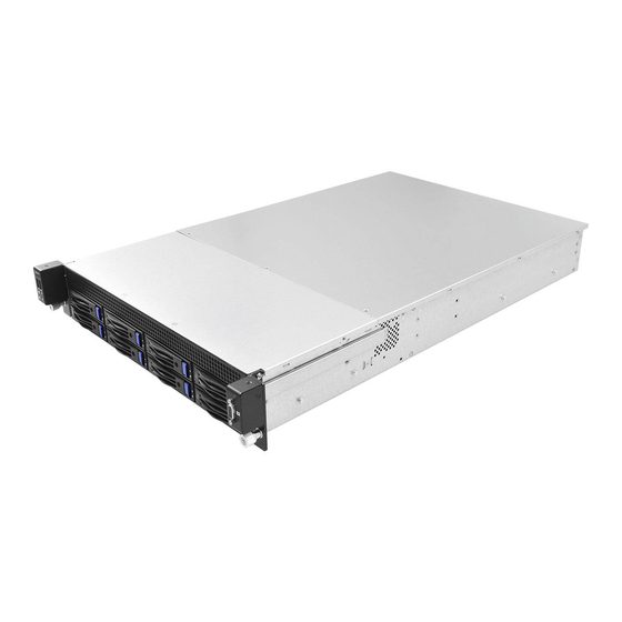
2U4FH-8L Chapter 1 Introduction Thank you for purchasing 2U4FH-8L, a reliable barebone system produced under ASRockRack’s consistently stringent quality control. It delivers excellent performance with robust design conforming to ASRockRack’s commitment to quality and endurance. 1. Because the hardware specifications might be updated, the content of this documentation will be subject to change without notice. -
Page 8: Shipping Box Contents
1.1 Shipping Box Contents Item Quantity 2U4FH-8L Barebone (2U form factor) System Boards (MB) Power Supply Units System Fans HDD Backplane (BPB) Front Panel Board (FPB) Power Distribution Boards (PDB) Power Cable, ATX 8Pin, PDB to MB, 200mm Power Cable, ATX 8Pin, PDB to MB, 700mm Power Cable, ATX 24Pin, PDB to MB, 520mm Power Cable, ATX 12Pin to 4*4Pin, PDB to BPB PMBus Cable, 1*5Pin, PDB to MB, 500mm... -
Page 9: Specifications
2U4FH-8L 1.2 Specifications 2U4FH-8L System Form Factor 2U Rackmount Chassis Model 2U4FH-8L Dimensions 28.1” x 17.6” x 3.4” (715 mm x 448 mm x 86 mm) (L/W/H, w/o ear) Support MB EEB, 12''x13'' Front Panel Buttons • Power Button • UID Button LEDs •... -
Page 10: Chapter 2 Server System Overview
Chapter 2 Server System Overview This chapter provides diagrams showing the location of important components of the server system. 2.1 System Components 2 x Power Supply Units Top Covers Riser Card Assembly Server Board 4 x System Fans 1 x VGA Port 8 x 3.5”... -
Page 11: Internal Features
2U4FH-8L 2.2 Internal Features... - Page 12 Item Server Board (SB) Riser Card Assembly Add-in Card Slots: 2 x PCIE Add-in Cards (on the riser card assembly)* Mezzanine Slot: 1 x Storage Mezzanine Card (on the server board)** Add-in Card Slots: 2 x PCIE Add-in Cards (on the riser card assembly)* Mezzanine Slot: 1 x LAN Mezzanine Card (on the server board)** Power Supply Unit (PSU2) Power Supply Unit (PSU1)
-
Page 13: System Front Panel
2U4FH-8L 2.3 System Front Panel HDD4 HDD5 HDD6 HDD7 HDD0 HDD1 HDD2 HDD3 Description Control Panel Buttons and LEDs 2 x USB 2.0 Ports 8 x 3.5" Hot-Swap HDD Trays (HDD0~HDD7) VGA Port 2.4 System Rear Panel Redundant PSU 1+1: Only one PSU is allowed to be removed while the server is running. -
Page 14: Front Control Panel Buttons And Leds
2.5 Front Control Panel Buttons and LEDs Front Control Panel Description LAN1, LAN2 Activity LED* System Health LED* USB 2.0 Port (USB1) USB 2.0 Port (USB2) Power Button and LED UID Button and LED* VGA Port *Please be noted that the functions are supported depending on the type of the motherboard. UID Button Press the UID button to toggle the front panel UID LED and the baseboard UID LED on and off. -
Page 15: Psu Led
2U4FH-8L UID LED Status Description Blue System identification is active. System identification is disabled. System Health LED Status Description Solid Red There is a fault in the system. System is normally operating. LAN1, LAN2 LED Status Description Blinking Green Network access Solid Green MEZZ LAN1/LAN2 is present. -
Page 16: Inch Hard Drive Tray Leds
2.7 3.5-inch Hard Drive Tray LEDs Description HDD Power LED HDD Activity LED Status LED Definitions HDD Power LED Status Description Blue HDD powered-on No power to HDD HDD Activity LED Status Description Solid Green HDD active Blinking Green HDD accessing or reading HDD failed HDD powered-off... -
Page 17: Chapter 3 Hardware Installation And Maintenance
2U4FH-8L Chapter 3 Hardware Installation and Maintenance This chapter helps you assemble the chassis and install components. Before You Begin Before you work with the server, pay close attention to the “Important Safety Instructions” at the beginning of this manual. 1. -
Page 18: Server Top Cover
3.1 Server Top Cover Removing the Server Top Covers 1. Before removing the top cover, power off the server and unplug the power cord. 2. The system must be operated with the chassis top cover installed to ensure proper cooling. 1. - Page 19 2U4FH-8L 3. When the top rear cover has been removed, you can also remove the top front cover. Remove the two screws on both sides that secure the front top cover to the chassis. 4. Push the front top cover toward the rear side to remove the cover from the locked position.
- Page 20 Installing the Server Top Cover 1. Lower the top front cover on the chassis, making sure the side latches align with the cutouts. Slide the top front cover toward the front. 2. Secure the front top cover with the two screws.
- Page 21 2U4FH-8L 3. Lower the top rear cover on the chassis, making sure the side latches align with the cutouts. Slide the top rear cover toward the front. 4. Secure the both covers with the screws.
-
Page 22: Hard Drive
3.2 Hard Drive 3.2.1 Installing a Hard Disk Drive into 3.5" Hard Drive Tray The system supports hot-swappable 3.5" hard drives. Removing 3.5” Hard Drive Trays from the Chassis 1. Press the locking lever latch on the drive tray to unlock the retention lever. 2. - Page 23 2U4FH-8L Installing a 3.5” Hard Drive to the Hard Drive Tray 1. Place a 3.5" HDD into the tray with the printed circuit board side facing down. Carefully align the mounting holes in the hard drive and the tray. 2. Secure the hard drive using four screws. 3.
- Page 24 3.2.2 Installing a Hard Disk Drive into 2.5" Hard Drive Carrier The system supports 2.5" PCIE SSDs. Removing 2.5” SSD Carriers from the Chassis 1. Remove the screws that secures the SSD carrier.
- Page 25 2U4FH-8L Installing a 2.5” SSD to the SSD Carrier 1. Place a 2.5" PCIE SSD into the carrier with its connector end toward the rear of the carrier where the mounting hole is located. Carefully align the mounting holes on the SSD and the carrier. 2.
-
Page 26: Power Supply
3.3 Power Supply The system can accommodate two AC or two DC power supplies in the bay at the rear of the chassis. Each unit provides up to 750 Watts of power. Only a single power supply is required for operation, with the second power supply purely as a redundant, load-sharing backup. - Page 27 2U4FH-8L Installing the Power Supply Unit Align the power supply unit with the power supply slot. Ensure that the LED appears on the lower right corner when you are installing the power supply unit. Carefully slide the PSU all the way into the power supply bay until it clicks into place.
-
Page 28: Add-In Card
3.4 Add-In Card 1. You can install up to four PCIE add-in cards to the chassis when they are installed on the provided riser card assembly. 2. Before installing an add-in card, power off the server and unplug the power cord. Installing an add-in card 1. - Page 29 2U4FH-8L 3. Remove the screw securing the filler plate. 4. Push to release the the filler plate from the assembly. 5. Slide the filler plate out sideways. 6. Install an add-in card into the retainer plate and into the connector on the riser card assembly.
- Page 30 8. Place the assembly back into the chassis and secure it with a screw.
- Page 31 2U4FH-8L 3.5 Mezzanine Card Installing a Mezzanine Card You can use an optional Ethernet mezzanine card for additional LAN ports or an optional storage mezzanine card for additional hard drives. Please be aware that the LAN mezzanine card must be used in conjunction with a matching I/O module. 1.
- Page 32 Tighten the screw to secure the matching I/O module to the chassis. I/O Module...
-
Page 33: System Fan
2U4FH-8L 3.6 System Fan Replacing the System Fan 1. Unplug the fan connecter and remove the failed fan. 2. Align the fan mounts on the fan bar with the mounting holes on the replacement fan. 3. Gently place the fan on the fan bar. Make sure the fan is well seated. 4. -
Page 34: Server Board
3.7 Server Board Follow the steps below to install the server board to the chassis. 1. Hold the server board only by the edges. 2. Gently place the server board into the chassis. Sit the server board on the server board tray. -
Page 35: Chassis Cables
2U4FH-8L 3.8 Chassis Cables This section lists supported cables for your chassis system. Cable type and quantity vary depending on the server board that comes with your system. BPB Cable, MiniSAS HD to 8087(L/A) (650mm) (Quantity: 1) Backplane Server Board BPB Cable, MiniSAS HD to 8087(R/A) (650mm) (Quantity: 1) Backplane Server Board... - Page 36 USB Cable (1250mm) (Quantity: 5) Server Board VGA Cable (850mm) (Quantity: 1) Front Panel Server Board Power Cable, ATX 8Pin (200mm) (Quantity: 1) Server Board Power Cable, ATX 8Pin (700mm) (Quantity: 1) Server Board Power Cable, ATX 24Pin (520mm) (Quantity: 1) Server Board PMBus Cable (500mm) (Quantity: 1) Server Board...
- Page 37 2U4FH-8L Power Cable, ATX 12Pin to 4*4Pin (Quantity: 1) 2.5" SSD Cables, SATA 7+15 to 7Pin+1*4Pin (650mm) (Quantity: 2) PCIE SSD Add-in Card 2.5" SSD Cables, SATA 7+15 to 7Pin+1*4Pin (800mm) (Quantity: 2) PCIE SSD Add-in Card Connections and cable routing may differ depending on various server boards. Please refer to the Quick Installation Guide to know the exact headers or connectors to be connected on the server board you purchase.
- Page 38 Chapter 4 Backplane Specifications 4.1 Hard Drive Backplanes (BPB) Top View PWR_HDD3 PWR_HDD4 PWR_HDD5 PWR_HDD6 PWR_HDD7 HBA1 PWR_HDD2 PWR_HDD1 BMC_SMB1 HBA0 Description SSD Power Connector (PWR_HDD4) HDD Power Connector (PWR_HDD2) HDD Power Connector (PWR_HDD3) HDD Power Connector (PWR_HDD1) SSD Power Connector (PWR_HDD5) Mini-SAS HD Connector (HBA1) Mini-SAS HD Connector (HBA0) SSD Power Connector (PWR_HDD6)
- Page 39 2U4FH-8L 4.2 Front Panel Board (FPB) Top View USB_HEADER1 AUX_PANEL1 Description Front and Auxiliary Panel Header (AUX_PANEL1) USB Header (USB_HEADER1) 4.3 Power Distribution Board (PDB-D) Top View CON2 ATX12V2 ATX12V1 PWR_HDD1 ATXPWR1 PSU2 CON1 Description ATX 8pin Power Connector (ATX12V1) ATX 8pin Power Connector (ATX12V2) PMBus Connnector (J1) HDD Power Connector (PWR_HDD1)
- Page 40 4.4 PCIE SSD Add-In Card (PE-SSD) (Optional) The PCIE SSD add-in card is used only when you need to install SSDs on the system. Top View HS_DET_1 PE_SSD0 PE_SSD1 Description Hot Plug Detection Header (HS_DET_1) SSD Signal Connector (PE_SSD0) SSD Signal Connector (PE_SSD1)
- Page 41 2U4FH-8L 4.4 Pin Definitions HDD Power Connectors The 4-pin connectors (PWR_HDD1) provide power to the (PWR_HDD2) backplane. GND1 (PWR_HDD3) GND2 +12V SSD Power Connectors The 4-pin connectors pro- (PWR_HDD4) vide power to the SSDs. (PWR_HDD5) +12V_HDD (PWR_HDD6) (PWR_HDD7) +5V_HDD MiniSAS HD Connectors These connectors are used (HBA0) to connect a mini-SAS HD...
- Page 42 Front and Auxiliary Panel This header supports multiple Header functions on the front panel. (19-pin AUX_PANEL1) ATX Power Connector The PDB provides a 24-pin ATX (24-pin ATXPWR1) power connector. To use a 20-pin ATX power supply, please plug it along Pin 1 and Pin 13. ATX 12V Power The PDB provides two 8-pin +12V2...
- Page 43 2U4FH-8L Hot Plug Detection PV_VCCIO The header is used for PCIE Header SMB_CPU_PCIE_CLK Hot Swap for Purley. SMB_CPU_PCIE_DTA (4-pin HS_DET_1) SSD Signal Connectors These connectors are used (PE_SSD0) to connect a SSD signal (PE_SSD1) cable to the SDDs.
Need help?
Do you have a question about the Rack 2U4FH-8L and is the answer not in the manual?
Questions and answers