
Summary of Contents for Park-Daddy PD50AA
- Page 1 07.10.2017 Manual Version: Park Daddy Installation Manual MODEL PD50AA MODEL PD100AA...
-
Page 2: Table Of Contents
TABLE OF CONTENTS Introduction.………………………......…………………….…………2 Package Contents…………………………......……………..………3 Unpacking……………………………......…………………….….…..3 Installing Infrared Head Units..…....…………………………….…4 Installing RF Radio Receivers……....………………………….…10 Operation………………………………......…………………..……..12 Alternative Uses…………..…….......……………………….….……13 Programming Alternative Channels………....…………..……….14 Restoring Factory Channel Settings……....………………..……15 Warnings…………….………………………......…….………...…16 Product Care…………………………………......…..……….….17 Troubleshooting…………………….......………………….……..….18 Warranty……………………….……......……….…….…..……..….20 Disclosures…………………………......……………………….……20 Customer Service…………………......………….….………………20 Technical Specifications………….……....…..…..……………..…21 FCC & IC Warnings…..……………......…………….……..……..22 Mounting Template…..……………......…………….……..…….23 INTRODUCTION Thank you for purchasing this product from VOXX Electronics. -
Page 3: Package Contents
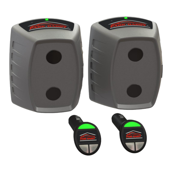
PACKAGE CONTENTS (1) Receiving Infrared Head Unit “A” (1) Transmitting Infrared Head Unit “B” (2) RF Radio Receivers (4) 1” #8 Pan Head ScrewsS (4) Screw Anchors (See Figure 1 and Figure 2) UNPACKING 1. The product contents are set in a cardboard tray. Carefully remove all of the parts in the tray. -
Page 4: Installing Infrared Head Units
The Park-Daddy® Vehicle Parking System can be used in garages with up to 4 parking spots across. The Park-Daddy® can also be used as an invisible barrier in the front and the side of the vehicle to warn you when a vehicle is close to objects placed in the garage. For installation instructions for the other alternative uses, please refer to the Alternative Uses section. - Page 5 DETERMINING VEHICLE CLEARENCE Locate Mounting Template at the end of this User Manual. The distance from the inner part of the garage door and line “B” of the Mounting Template can be determined by the following: 1. With the garage door in the closed position, determine the inner most point of the interior section of the garage door including handles, hinges, supports, hurricane struts or trusses and any other protrusion attached to the interior of the door.
- Page 6 Figure 3...
- Page 7 HEIGHT POSITIONING Determine the height of the head units. At least one of the two lenses should be at the same height of the face of the rear bumper. An average height rear bumper for most passenger cars up to standard size two-wheel drive pickup trucks is 20 to 22 inches from the floor to line “C”...
- Page 8 MOUNTING METHODS There are two different Mounting Methods. First cut out the Mounting Template along Line “A” before proceeding. METHOD #1 This method is for easy mounting to painted surfaces with smooth to medium textures such as painted wood, drywall with or without texture, concrete or concrete blocks and bricks.
- Page 9 METHOD #2 This method is for mounting to surfaces with a heavy or course textures or for easy and frequent removals. 1. With the Mounting Template cut out, hold the Mounting Template on the mounting wall and line up line “B” to the distance measurement and line up line “C”...
-
Page 10: Installing Rf Radio Receivers
The Infrared Head Units are now mounted and should be automatically paired. To confirm that the Infrared Head Units are paired, you will see a short green flash every 15 seconds from the LEDs on the top of each Infrared Head Unit. If the LED on Infrared Head Unit “A”... - Page 11 If either one of the functions above are not operating correctly, refer to the Trouble Shooting section of this User Manual. You are now ready to proceed to the Operation section.
-
Page 12: Operation
Infrared Head Units mounted in the garage to notify the operator of a vehicle when the rear bumper has cleared the garage door opening. Before using the Park-Daddy® for the first time, release the garage door from the garage door opener and manually check the clearance between the vehicles and the garage door. -
Page 13: Alternative Uses
ALTERNATIVE USES The Park-Daddy® Vehicle Parking System can also be used as a safety barrier for the side or the front of vehicles, notifying the operator of any obstructions. These alternative uses are not suggested unless the operator has adequate reflexes to stop the vehicle when the barrier has been crossed. -
Page 14: Programming Alternative Channels
PROGRAMMING ALTERNATIVE CHANNEL An Alternative Channel can be programmed to the system in the event another Park-Daddy® system is in operation in the close vicinity and is causing interference while operating your system. To program an alternative channel, follow these steps: 1. -
Page 15: Restoring Factory Channel Settings
RESTORING FACTORY CHANNEL SETTINGS To restore the Park-Daddy® system to the Factory Channel Settings, follow these steps: 1. Make sure the RF Radio Receivers being programmed are within 50 feet of the Infrared Head Units and no vehicles or any other objects are blocking the Infrared Head Units. -
Page 16: Warnings
WARNINGS • When using this product while sitting in a motor vehicle, check for pedestrians, pets and objects around you. • Roll back may occur when a vehicle is in the Park position and the brake is released. Always let the vehicle settle into position before shutting off the vehicle. It is always good practice to add a 1 inch safety margin plus a 3 inch roll back margin to insure a safe clearance from the interior of the garage door to the outer most point of your rear bumper when installing Infrared Head Units. -
Page 17: Product Care
• Do not attempt to park more than one vehicle at the same time using a single system or multiple systems. • Although a very rare occurrence, infrared signals emitted from the Park-Daddy can cause interference to the garage door opener safety sensors. Be sure to check the functionality for the garage door safety sensors after installation. -
Page 18: Troubleshooting
2. Check to see if the batteries are in the proper position. D. Garage door opener malfunctions after installing the Park-Daddy®. Although a very rare occurrence, the Park-Daddy® could interfere with the garage door safety sensors causing a malfunction. Swap Infrared Head Unit A with Infrared Head Unit B and vice versa. - Page 19 F. No color illuminating from the Status Indicator, but the tone sounds on the RF Radio receiver. Internal problem - Call Customer Service. G. Volume control does not work and/or no tone sounding, but the Status Indicator illuminates on the RF Radio Receiver. Internal problem - Call Customer Service.
-
Page 20: Warranty
90-DAY LIMITED WARRANTY PARK-DADDY® VOXX ELECTRONICS CORPORATION warrants this product to be free of defects in parts and workmanship for 90-days from date of purchase. If it becomes necessary to return the product for service or replacement during the warranty period, contact the Customer Service Department by calling 1-800-371-7725 for a return authorization. -
Page 21: Technical Specifications
TECHNICAL SPECIFICATIONS Operating Temperature Range: -4 - 130⁰F (-20 - 54⁰C) Total Shipping Weight: 2.6 Lbs. (1.2 Kg) IR Head Unit Pairing Range: 5 – 100 ft. (1.5 – 30.5 m) Precision Over Full Pairing Range: Approximately 1/8 in. (3.2 mm) IR Head Unit Battery Requirements: (2) D Size Alkaline Batteries per Unit... -
Page 22: Fcc & Ic Warnings
FCC WARNINGS CAUTION: VOXX ELECTRONICS CORPORATION is not responsible for any changes or modifications not expressly approved by the party responsible for compliance. Such modifications could void the user’s authority to operate the equipment. RADIO AND TELEVISION INTERFERENCE This equipment has been tested and found to comply with the limits, pursuant to Part 15 of the FCC rules. These limits are designed to provide reasonable protection against harmful interference in a residential installation.
Need help?
Do you have a question about the PD50AA and is the answer not in the manual?
Questions and answers