Table of Contents
Advertisement
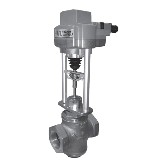
ELECTRIC ACTUATOR
E024, EO25, E026, EO29 & E031
Installation Operation and Maintenance Instructions
TABLE OF CONTENTS
Electric Actuator Specifications....................................................2
Overview ..............................................................................................3
Actuator Wiring Diagrams - Proportional Control .................4
VMS-50 BCM Specifications & Wiring Diagram .......................5
VMS-50 PS Specifications ...............................................................5
VMS -50 BCM Battery Replacement ............................................7
Removal of E024 & E025 .................................................................8
Installation of E024 & E025 ............................................................9
Removal of E026, E029 & E031....................................................10
Installation of E026, E029 & E031 ...............................................11
Set-up ..................................................................................................12
Control Action ..................................................................................13
Power Failure Direction E025 & E026 .......................................14
Indicator Lights ................................................................................15
Installation Drawings .............................................................. 16-17
On-Off Control ........................................................................... 21-25
HVAC_BAC_ELECTRIC_IOM_RevE_0421
92500115 RevF
Advertisement
Table of Contents

Subscribe to Our Youtube Channel
Related Manuals for Warren Controls E025


Summary of Contents for Warren Controls E025
-
Page 1: Table Of Contents
Removal of E026, E029 & E031............10 Installation of E026, E029 & E031 ..........11 Set-up ....................12 Control Action ..................13 Power Failure Direction E025 & E026 ........14 Indicator Lights ................15 Installation Drawings .............. 16-17 Removal & Installation of Actuator & Linkage Base ..18-20 On-Off Control ................ -
Page 2: Electric Actuator Specifications
______________________________________________________________________________________________ Capacitor: E025, E026 Capacitor charge time 5 to 20 seconds ______________________________________________________________________________________________ Manual Override: Yes, with supplied Allen Key (4mm E024, E025 / 5mm, E026, E029, E031) ______________________________________________________________________________________________ Construction: Aluminum die cast Yoke, plastic Housing ______________________________________________________________________________________________ Connections: 3 foot long 4 Conductor 18 gauge wire, pigtail (may include fifth pink colored conductor only used for factory programming. -
Page 3: Overview
Button is pressed, the actuator completely down will drive one full cycle to throughout travel for its mechanical end stops OR E025 AND E026 actuators E025 the valves mechanical seats. with CAPACITORS. Upon completion of this cycle E026 the actuators working range... -
Page 4: Actuator Wiring Diagrams - Proportional Control
ACTUATOR WIRING DIAGRAMS ACTUATOR WIRING DIAGRAMS - PROPORTIONAL CONTROL Note: For On-Off Control see Pages 21-25 2-10 VDC To Back-Up Control Module ACTUATOR Common BK #1 ( ) NEUTRAL LINE RD #2 ( ) 24 VAC CLASS 2 TRANSFORMER 2-10 VDC CONTROL SIGNAL Input, 2 to 10 VDC... -
Page 5: Vms-50 Bcm Specifications & Wiring Diagram
SPECIFICATIONS (Back-Up Control Module) VMS-50 BCM SPECIFICATIONS Actuator Usage: Models E024, E029 or E031 (NOTE: E031 is an E029 Actuator with a VMS-50-BCM. This does not include the VMS-50-PS.) Power Requirement: 24 Vdc 2.0 A from Separate External; Switching Power Supply VMS-50 BCM Power Output: 24 Vdc 48W Total... -
Page 6: Vms -50 Bcm Installation & Replace Battery Led Function
INSTALLATION - PROPORTIONAL CONTROL 1. Disengage the building power circuit before wiring. Verify that the battery inside the VMS-50 BCM has its wires disconnected and leave them that way for now. Disconnect them if they are connected. 2. Connect the VMS-50 BCM to the actuator(s) as shown on wiring diagram. The VMS-50 BCM can power one, two or three actuators. Actuator A: Connect Relay 1 Normally Open Contact RELAY 1 NO to white wire from actuator to drive the valve stem in the direction determined by the actuator rotation switch position. -
Page 7: Vms -50 Bcm Battery Replacement
VMS-50 BCM (SP12-1.2 (12V1.4 AH/T1)) BATTERY REPLACEMENT PROCEDURE: NOTE: Normal valve operation under 24 Vdc power need not be interrupted during battery replacement; however, the fail-safe function will not be avail- able until the new battery is in place, connected and sufficiently charged (typi- cally 2-4 hours). -
Page 8: Removal Of E024 & E025
2) Operate actuator so plug is off seat(s) or travel stop in valve. WARNING: DO NOT LOOSEN THE FACTORY SET 3) Remove power and signal from actuator. For E025, after power ADJUSTABLE HEIGHT SCREWS ON THE SIDES OF is removed, cycle Fail-Safe Switch from Up Arrow to Down THE ACTUATOR YOKE LINKAGE. -
Page 9: Installation Of E024 & E025
READ ALL INSTRUCTIONS CAREFULLY BEFORE BEGINNING. INSTALLATION OF E024 & E025 ACTUATORS ON THE VALVE 6) Rotate actuator to desired orientation. For the factory default SEE DRAWING D3400024 on page 16 actuator position the motor electrical wire end of the actuator THESE INSTRUCTIONS TREAT THE ACTUATOR (ITEM 1) AND LINKAGE BASE faces the outlet side of a 2-way valve, common “C”... -
Page 10: Removal Of E026 & E029/E031
READ ALL INSTRUCTIONS CAREFULLY BEFORE BEGINNING. REMOVAL OF E026 & E029/E031 ACTUATORS FROM VALVE 6) Loosen yoke locknut (Item 4) until it is free of bonnet. SEE DRAWING D3400025 on page 17 7) Remove spacer ring (Item 3). 1) Remove line pressure and isolate valve in piping. 8) Remove actuator from valve. -
Page 11: Installation Of E026, E029 & E031
READ ALL INSTRUCTIONS CAREFULLY BEFORE BEGINNING. INSTALLATION OF E026 & E029/ E031 ACTUATORS ON THE VALVE SEE DRAWING D3400025 on page 17 6) Rotate actuator to desired orientation. For the factory default actuator position the motor electrical wire end of the actuator THE SILVER SPACER RING THAT COMES WITH THE ACTUATOR MUST BE faces the outlet side of a 2-way valve, common “C”... -
Page 12: Set-Up
SET-UP Prior to enabling the power perform the following check: Verify the Control Signal. The default Control Signal is 2-10 Vdc (see the wiring diagram for 4-20 mAdc). Review the Control Action by inspecting the Rotation Switch position. Confirm the Power Failure mode by inspecting the Fail-Safe switch. Verify that the actuator is correctly installed on the valve body Enable the Power Source. -
Page 13: Control Action
CONTROL ACTION - PROPORTIONAL CONTROL E024, E025, E026, E029 & E031 Actuators - Rotation Switch position. How the valve and actuator react to the Control Signal. The Fail-Safe position during Loss of Power and Loss of Signal are identical for an E024 and E029/E031 with VMS-50 BCM. For on-off con- trol see Addendum B on pages 21-25. -
Page 14: Power Failure Direction E025 & E026
POWER FAILURE E025 & E026 Actuators - Fail-Safe Switch position: Valve and actuator Power Failure Direction. DESCRIPTION FACING Up Arrow Power Failure Direction is Fail Open (FO) 2-way valves and Upper Port (E025 & E026) Closed for 3-way valves. Down Arrow Power Failure Direction is Fail Closed (FC) for 2-way valves and Lower (E025 &... -
Page 15: Indicator Lights
STATUS ADAPTION/ POWER DESCRIPTION (yellow LED) (green LED) ILLUMINATED Normal (no faults) BLINKING Power Failure is active ( E025 & E026 only) ILLUMINATED Fault is detected No Power or Capacitors charging ILLUMINATED ILLUMINATED Auto-Calibration is running NOTE: 1) Verify Control and Feedback Wiring and Signals if a Fault is detected. -
Page 16: Installation Drawings
D3400024 2600 Emrick Blvd • Bethlehem, PA 18020 • USA • 800-922-0085 • www.warrencontrols.com... - Page 17 D3400025 HVAC_BAC_ELECTRIC_IOM_RevE_0421...
-
Page 18: Removal & Installation Of Actuator & Linkage Base
2) Operate actuator (Item 1) so plug is off seat(s) or travel stop in valve. 3) Remove power and signal from actuator. For E025, after power is removed, cycle Fail-Safe Switch from Up Arrow to Down Arrow until actuator stem no longer moves. Adaption/ 7) Press together the linkage base tracks and slide the actuator Power (green LED) changes from blinking to off. - Page 19 REMOVAL & INSTALLATION OF ACTUATOR & LINKAGE BASE READ ALL INSTRUCTIONS CAREFULLY BEFORE BEGINNING. SEE DRAWING D3400024 on page 16 7) Press the manual override button then use the actuator manual override to lower the stem connector until a slight resistance is felt.
- Page 20 REMOVAL & INSTALLATION OF ACTUATOR AND LINKAGE BASE READ ALL INSTRUCTIONS CAREFULLY BEFORE BEGINNING. 10) Press the first threaded linkage nut into the socket on the actuator rail and hold. The dovetail on the threaded linkage 13) Lock stem connector clamp, use fingers on the front and nut must fully engage the groove on the linkage base track.
-
Page 21: On-Off Control
ON-OFF CONTROL ON / OFF CONTROL ACTUATOR BK #1 ( ) Common NEUTRAL LINE RD #2 ( ) 24 VAC CLASS 2 TRANSFORMER RELAY WH #3 (Y) Input, 2 to 10 VDC 2-10 VDC FEED BACK OR #5 (U) Output, 2 to 10 VDC SIGNAL HVAC_BAC_ELECTRIC_IOM_RevE_0421... - Page 22 ON-OFF CONTROL VMS-50 OUTPUT TO OUTPUT TO OUTPUT TO OUTPUT TO OUTPUT TO OUTPUT TO ACTUATOR ACTUATOR ACTUATOR C ACTUATOR C ACTUATOR ACTUATOR A A (IF USED) (IF USED) (IF USED (IF USED) ) 24 VDC RELAY 1 24 VDC 24 VDC RELAY 2 RELAY 3...
- Page 23 ON-OFF CONTROL 1. Disengage the building power circuit before wiring. Verify that the battery inside the VMS-50 has its wires disconnected and leave them that way for now. Disconnect them if they are connected. 2. Connect the VMS-50 BCM to the actuator(s) as shown on wiring diagram. The VMS-50 BCM can power one, two or three actuators. Actuator A: Connect 24 Vdc (+) OUT 24 VDC + to red wire from actuator to provide power.
- Page 24 Closes 2-way valves and Closes Lower port 3-way valves. → Facing Up Arrow See POWER FAILURE E025 & E026 actuators – Fail-Safe Switch position PG (E025 & E026) Facing Down Arrow See POWER FAILURE E025 & E026 actuators – Fail-Safe Switch position PG (E025 &...
- Page 25 ON-OFF CONTROL (E024 and E029, E031) HVAC_BAC_ELECTRIC_IOM_RevE_0421...
- Page 26 NOTES 2600 Emrick Blvd • Bethlehem, PA 18020 • USA • 800-922-0085 • www.warrencontrols.com...
- Page 27 NOTES HVAC_BAC_ELECTRIC_IOM_RevE_0421...
- Page 28 HVAC_BAC_ELECTRIC_IOM_RevE_0421 2600 EMRICK BLVD • BETHLEHEM, PA 18020 • USA •800-922-0085 • WWW.WARRENCONTROLS.COM DEPENDABLE, RUGGED, PRECISION CONTROL VALVES AND ACCESSORIES...
Need help?
Do you have a question about the E025 and is the answer not in the manual?
Questions and answers