Table of Contents
Advertisement
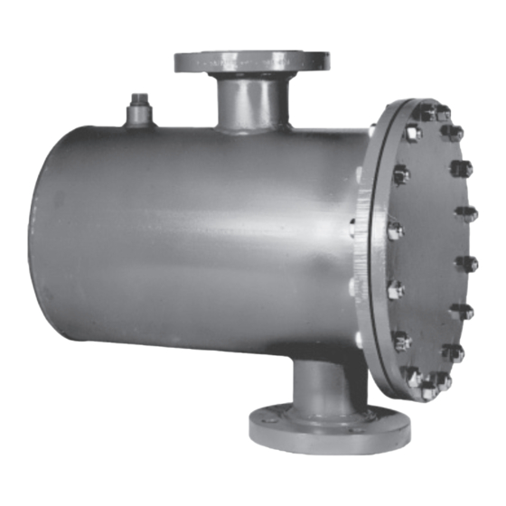
PRODUCT OVERVIEW
This document covers the installation, operation and maintenance
of 313 Overflow Traps presented in the "Level Controls and
Accessories", Product Specification.
GENERAL INFORMATION
The instructions given herein cover generally the operation and
maintenance of subject equipment. Should any questions arise
which may not be answered specifically by these instructions,
they should be referred to Warren Controls Inc. for further detailed
information and technical assistance. This manual cannot possibly
cover every situation connected with the operation, adjustment,
inspection, test, overhaul and maintenance of the equipment
furnished. Every effort is made to prepare the text of this manual
so that engineering and design data is transformed into the most
easily understood wording. Warren Controls Inc., in furnishing this
equipment and this manual, must presume that the operation and
maintenance personnel assigned thereto have sufficient technical
knowledge and experience to apply sound safety and operational
313 OVERFLOW TRAP
INSTALLATION, OPERATION
& MAINTENANCE INSTRUCTIONS
TABLE OF CONTENTS
Overview .................................................Cover
General Information ............................Cover
Installation .......................................................4
Operation .........................................................4
Maintenance ...................................................4
Float Ball Level Test Procedure .................5
Information Present on 313's ....................7
Overflow Trap Specifications.....................8
Overhaul / Parts Kits ...........................9 & 10
Drawings..................................................11-14
practices which may not be covered herein. In applications where
Warren Controls Inc. furnished equipment is to be integrated with a
process or other machinery, these instructions should be thoroughly
reviewed to determine the proper integration of the equipment into
the overall plant operational procedures. Warren Controls does not
assume responsibility for the selection, use, or maintenance of any
product. Responsibility for proper selection, use, and maintenance
of any Warren Controls product remains solely with the purchaser
and end-user.
313_IOM_RevC_0418
Advertisement
Table of Contents

Related Manuals for Warren Controls 313


Summary of Contents for Warren Controls 313
-
Page 1: Table Of Contents
Drawings..........11-14 313_IOM_RevC_0418 PRODUCT OVERVIEW This document covers the installation, operation and maintenance of 313 Overflow Traps presented in the “Level Controls and Accessories”, Product Specification. GENERAL INFORMATION practices which may not be covered herein. In applications where The instructions given herein cover generally the operation and Warren Controls Inc. - Page 2 WARNING CHECK OVERFLOW TRAP FOR ANY DAMAGE DUE TO IMPROPER STORAGE OR TRANSPORTATION. IMMEDIATELY NOTIFY YOUR SALES ORGANIZATION OF ANY DAMAGED GOODS UPON RECEIPT. DO NOT ATTEMPT TO MOVE OR DISTURB THE OVERFLOW TRAP FURTHER SO PHOTOS MAY BE TAKEN. IF THE SHIPPING CONTAINER IS NOTICEABLY DAMAGED REFUSE RECEIPT, AS THE SHIPPING COMPANY SHOULD BE HELD LIABLE UNTIL A SHIPPING REPRESENTATIVE IS...
- Page 3 The [C] 313 Overflow Trap traps and relieves this condensate through its internal pilot without the steam blanket escaping. Overflow can occur if the water entering the tank exceeds its capacity. The 313 Overflow Trap relieves the overflow through its internal single seated main stage valve. Falling liquid levels and condensing steam can cause a vacuum that can damage the tank.
-
Page 4: Installation
Overflow can occur if the water entering the tank exceeds its capacity. The 313 Overflow Trap relieves the overflow through its internal single seated main stage valve. Buoyancy of the overflow trap’s internal float ball provides force to actuate the internal pilot operated single seated valve assembly to relieve condensate and overflow to drain. -
Page 5: Float Ball Level Test Procedure
BOTTOM OF VALVE BODY BOTTOM OF FLOAT BALL BETWEEN 0.080 INCHES BELOW AND 0.102 INCHES ABOVE BOTTOM OF VALVE BODY BOTTOM OF FLOAT BALL BETWEEN 0.590 INCHES ABOVE AND 0.720 INCHES ABOVE BOTTOM OF VALVE BODY Level Controls - IOM 313 313_IOM_RevC_0418... -
Page 6: Float Ball Level Adjustment Procedure
FLOAT BALL LEVEL ADJUSTMENT PROCEDURE 1) Remove line pressure and isolate overflow trap. (It is recommended that you have an Inspection Kit on hand before beginning the procedure.) 2) Remove nuts and bolts from end cover. 3) Remove end cover from float chamber. 4) Remove end cover gasket. -
Page 7: Information Present On 313'S
There may also be other numbers and marks present that do not provide useful information. Customer specific tagging may also present. The labels or plates used, and information present, on Warren Controls other product lines or older overflow traps may be different, contact the factory for details. FACTORY SERIAL... -
Page 8: Overflow Trap Specifications
Serial number label located here Deaerators, tanks with steam blankets, produce additional liquid as the steam condenses. The 313 Overflow Trap traps and relieves this condensate through its internal pilot without the steam blanket escaping. Buoyancy of its float ball provides force to actuate internal pilot operated single seat valve assembly to relieve condensate and overflow to drain. -
Page 9: Overhaul / Parts Kits
313 OVERFLOW TRAP PARTS / OVERHAUL (REFER TO DRAWING 03130611101) Damaged or worn parts can decrease performance and shorten the life of the overflow trap. A damaged float ball can result in the inadequate removal of condensate and overflow. A damaged or worn end cover gasket or inner valve body gasket can cause external leakage resulting in damage to surrounding equipment and the loss of the steam blanket from the tank. - Page 10 313 INSPECTION KIT - SEE DWG 03130611101 ITEM DESCRIPTION ITEM DESCRIPTION INNER VALVE BODY GASKET END COVER GASKET 313 FLOAT BALL KIT - SEE DWG 03130611101 ITEM DESCRIPTION ITEM DESCRIPTION FLOAT BALL END COVER GASKET INNER VALVE BODY GASKET...
-
Page 11: Drawings
DRAWING 03130611101-1 Level Controls - IOM 313 313_IOM_RevC_0418... - Page 12 DRAWING 03130611101-2 2600 Emrick Blvd • Bethlehem, PA 18020 • USA •800-922-0085 • www.warrencontrols.com...
- Page 13 DRAWING 03130611101-3 Level Controls - IOM 313 313_IOM_RevC_0418...
-
Page 14: Drawings
DRAWING 03130614111 2600 Emrick Blvd • Bethlehem, PA 18020 • USA •800-922-0085 • www.warrencontrols.com... -
Page 15: Iom_Revc
NOTES Level Controls - IOM 313 313_IOM_RevC_0418... - Page 16 313_IOM_RevC_0418 2600 EMRICK BLVD • BETHLEHEM, PA 18020 • USA •800-922-0085 • WWW.WARRENCONTROLS.COM DEPENDABLE, RUGGED, PRECISION CONTROL VALVES AND ACCESSORIES...
Need help?
Do you have a question about the 313 and is the answer not in the manual?
Questions and answers