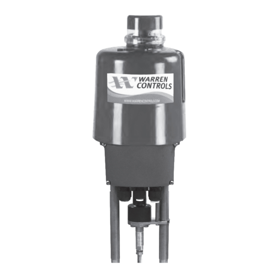
Table of Contents
Advertisement
Quick Links
Installation Instructions for ILEA electric actuators
TABLE OF CONTENTS
Designations .................................................... 2
Symbols and Safety ....................................... 2
Actuator Mounting ........................................ 3
General Safety ................................................. 4
Wiring & Commissioning ............................. 5
Symbols and Safety ....................................... 5
Tracing Faults Charts ................................. 6-7
ILEA-A
x
ILEA-B
x
ILEA-P
x
ILEA-Q
x
ILEA_IOM_RevDc_0721
92500136 RevC
Advertisement
Table of Contents

Subscribe to Our Youtube Channel
Summary of Contents for Warren Controls ILEA-Ax
- Page 1 Installation Instructions for ILEA electric actuators ILEA-A ILEA-B ILEA-P ILEA-Q TABLE OF CONTENTS Designations ............ 2 Symbols and Safety ........2 Actuator Mounting ........3 General Safety ..........4 Wiring & Commissioning ......5 Symbols and Safety ........5 Tracing Faults Charts ......... 6-7 ILEA_IOM_RevDc_0721 92500136 RevC...
- Page 2 ACTUATOR PART DESIGNATIONS Pillar Coupling Clamping Screws Coupling Nut for Spring Pack Valve Stem Locking Nut Yoke Lock Nut Bracket Pillar Nut SYMBOLS AND SAFETY Please ensure that the detailed operating instructions and the chapter on “Safety” in particular have been read and understood by all personnel involved in the installation, start-up, operation, maintenance and repair of the actuators.
- Page 3 ACTUATOR MOUNTING When mounting an actuator on a valve, always BEFORE START WORKING: use the hand wheel! Motor operation during SAFETY REGULATIONS: mounting may cause injuries and damage to - Disconnect mains! actuator and valve! - Prevent reconnection! - Test for absence of harmful voltages! FOR MOUNTING THE ACTUATOR, THE VALVE - Cover or close nearby live parts! MUST BE IN FULLY CLOSED POSITION!
- Page 4 USB connection. If this is required, contact the Warren Controls factory. CONTROL SIGNAL AND POSITION FEEDBACK CHOICES AND LABEL DESIGNATIONS.
- Page 5 WIRING TERMINATION (A/B ONLY) Electric supply for 1-phase AC/DC 10 11 12 13 14 15 16 17 18 19 20 21 22 23 Button 24 V (OPTION) AC/DC 115V- 230V Control Position Binary Fail Actual Supply Signal Feedback Input safe Closed Open value...
- Page 6 18. Tracing faults TRACING FAULTS CHARTS (A/B ONLY) Red LED Green LED Status Probable reasons Possible remedy x x Actuator does not respond, both 1) No supply voltage applied 1) Check mains supply LEDs are off 2) The applied voltage does 2) Apply correct supply not match the actuator voltage voltage on the tag plate ...
- Page 7 TRACING FAULTS CHARTS (A/B ONLY) Red LED Green LED Faults within the actuator’s Probable reasons Possible remedy environment x x Actuator drives into a preset 1) Signal is applied to the 1) Disconnect the signal position binary fail‐safe input 2) Check supply voltage 2) Supply voltage failure on actuators with optional PSCP x ...
- Page 8 ILEA_IOM_RevDc_0721 92500136 RevC 2600 EMRICK BLVD • BETHLEHEM, PA 18020 • USA •800-922-0085 • WWW.WARRENCONTROLS.COM DEPENDABLE, RUGGED, PRECISION CONTROL VALVES AND ACCESSORIES...


Need help?
Do you have a question about the ILEA-Ax and is the answer not in the manual?
Questions and answers