Table of Contents
Advertisement
Available languages
Available languages
Quick Links
Advertisement
Chapters
Table of Contents

Related Manuals for WIKA A2G-100


Summary of Contents for WIKA A2G-100
- Page 1 Operating instructions Betriebsanleitung PID controller for the control of air flows or differential pressures, model A2G-100 PID-Regelgerät zur Regelung von Volumenströmen oder Differenzdruck, Typ A2G-100 Model A2G-100...
- Page 2 Operating instructions model A2G-100 Page 3 - 42 Betriebsanleitung Typ A2G-100 Seite 43 - 81 © 03/2018 WIKA Alexander Wiegand SE & Co. KG All rights reserved. / Alle Rechte vorbehalten. WIKA is a registered trademark in various countries. ® WIKA ist eine geschützte Marke in verschiedenen Ländern.
-
Page 3: Table Of Contents
2. Design and function 3. Safety 4. Transport, packaging and storage 5. Commissioning, operation 6. Menu navigation 7. Maintenance, cleaning and recalibration 8. Dismounting, return and disposal 9. Specifications Declarations of conformity can be found online at www.wika.com. WIKA operating instructions model A2G-100... -
Page 4: General Information
The general terms and conditions contained in the sales ■ documentation shall apply. Subject to technical modifications. ■ Further information: ■ - Internet address: www.wika.de / www.wika.com www.air2guide.com - Relevant data sheet: SP 69.11 WIKA operating instructions model A2G-100... -
Page 5: Design And Function
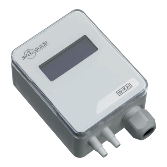
2.2 Description The model A2G-100 PID controller is used for the control of differential pressures or air flows in ventilation and air-conditioning applications. The 0 ... 10 V or 4 ... 20 mA control output is connected as control signal directly to the EC ventilation fan or frequency inverter (FI). -
Page 6: Safety
2 x 2 m PVC measuring hose (option) ■ Cross-check scope of delivery with delivery note. 3. Safety 3.1 Explanation of symbols WARNING! ... indicates a potentially dangerous situation that can result in serious injury or death, if not avoided. WIKA operating instructions model A2G-100... - Page 7 ... points out useful tips, recommendations and information for efficient and trouble-free operation. 3.2 Intended use The A2G-100 is a multi-functional PID controller for differential pressure or air flow control, specifically developed for the demands of the air-conditioning and ventilation industry.
- Page 8 Improper handling or operation of the instrument outside of its technical specifications requires the instrument to be taken out of service immediately and inspected by an authorised WIKA service engineer. The manufacturer shall not be liable for claims of any type based on operation contrary to the intended use.
- Page 9 The personnel trained by the operator are understood to be personnel who, based on their education, knowledge and experience, are capable of carrying out the work described and independently recognising potential hazards. Special operating conditions require further appropriate knowledge, e.g. of aggressive media. WIKA operating instructions model A2G-100...
- Page 10 Supply: DC 24 V / AC 24 V ±10 % < 1 W Made in EU E-Nr. 66209848 Model Measuring range Output signal Power supply Serial number Before mounting and commissioning the instrument, ensure you read the operating instructions! WIKA operating instructions model A2G-100...
-
Page 11: Transport, Packaging And Storage
Avoid exposure to the following factors: Direct sunlight or proximity to hot objects ■ Mechanical vibration, mechanical shock (putting it down hard) ■ Soot, vapour, humidity, dust and corrosive gases ■ Hazardous environments, flammable atmospheres ■ WIKA operating instructions model A2G-100... -
Page 12: Commissioning, Operation
Damage to the instrument When working on open electric circuits (printed circuit boards) there is a risk of damaging sensitive electronic components through electrostatic discharge. ▶ The correct use of grounded working surfaces and personal armbands is required. WIKA operating instructions model A2G-100... - Page 13 1. Instrument fixing at the desired mounting location (see chapter 5.1 “Instrument mounting”) 2. Opening the instrument cover, feeding the connection cable through the cable gland and connecting the wires to the terminal block (see chapter 5.2 “Electrical mounting”) WIKA operating instructions model A2G-100...
- Page 14 1. Select a mounting location (duct, wall, panel). 2. Remove the case cover and use the screw holes as a template. 3. Mount with suitable screws. Instrument fixing Instrument orientation WIKA operating instructions model A2G-100...
- Page 15 5. Commissioning, operation Application-related connections Static pressure Filter measurement/ Ventilator measurement/control control measurement/control WIKA operating instructions model A2G-100...
- Page 16 (SELV). Operate the PID controller in the middle of the measuring range, since deviations can occur at the range limits. Operate the A2G-100 with a constant operating voltage (±0.2 V) and ambient temperature. Prevent current/voltage spikes from switching the power supply on or off.
- Page 17 4 ... 20 mA 24 V Power supply AC/DC 24 V 0.0 V Time axis t [s] Pressure P Signal [I] 100 % 20.0 mA 50 % 12.0 mA 4.0 mA Time axis t [s] WIKA operating instructions model A2G-100...
- Page 18 5. Commissioning, operation 5.3 Output signal setting The analogue output signal of the model A2G-100 PID controller can be set between 0 ... 10 V and 4 ... 20 mA. The setting can be made via jumpers on the printed circuit board.
- Page 19 During the zero point setting the display and output value remains at the last measured value. The automatic zero point setting takes 3 seconds and is repeated every 10 minutes. Reset Reset (Zurücksetzen) WIKA operating instructions model A2G-100...
-
Page 20: Menu Navigation
PRESS.UNIT Move the “SELECT” button once, shortly, in order to activate the pressure unit selection. PRESS.UNIT ▶ Selection flashes Use “UP” or “DOWN” to find the desired pressure unit. ▶ Selection is displayed PRESS.UNIT mbar WIKA operating instructions model A2G-100... - Page 21 Use “UP” or “DOWN” to find the desired range. P OUTPUT MAX ▶ Selection is displayed 600 Pa Move the “SELECT” button once, shortly, in order to accept the selection. P OUTPUT MAX 600 Pa WIKA operating instructions model A2G-100...
- Page 22 Selection flashes Use “UP” or “DOWN” to find the desired response time. RESPONSE TIME ▶ 14 s Selection is displayed Move the “SELECT” button once, shortly, in order to accept the selection. RESPONSE TIME 14 s WIKA operating instructions model A2G-100...
- Page 23 Selection flashes Use “UP” or “DOWN” to find the desired set point. ▶ REF PRESSURE Selection is displayed 160 Pa Move the “SELECT” button once, shortly, in order to accept the selection. REF PRESSURE 160 Pa WIKA operating instructions model A2G-100...
- Page 24 “P-VALUE” selection. P-VALUE ▶ Selection flashes Use “UP” or “DOWN” to find the desired proportional band. P-VALUE ▶ Selection is displayed Move the “SELECT” button once, shortly, in order to accept the selection. P-VALUE WIKA operating instructions model A2G-100...
- Page 25 ▶ Selection flashes Use “UP” or “DOWN” to find the desired input damping. I-VALUE ▶ Selection is displayed 26.4 Move the “SELECT” button once, shortly, in order to I-VALUE accept the selection. 26.4 WIKA operating instructions model A2G-100...
- Page 26 D-VALUE ▶ 0.42 Selection is displayed Move the “SELECT” button once, shortly, in order to accept the selection. D-VALUE 0.42 9. Press the “SELECT” button in order to exit the SELECT menu. EXIT MENU WIKA operating instructions model A2G-100...
- Page 27 6. Menu navigation 6.2 Control variable 'air flow' 1. Select function mode of the A2G-100 Move the “SELECT” button in any direction for at least 2 seconds to activate the CONTROL UNIT mode. CONTROL UNIT ▶ Flow “CONTROL UNIT” is displayed ▶...
- Page 28 Use “UP” or “DOWN” to find the desired unit. ▶ Selection is displayed FORMULA UNIT m3/s Move the “SELECT” button once, shortly, in order to accept the selection. FORMULA UNIT m3/s When using the model A2G-FM measuring probe, activate the unit l/s. WIKA operating instructions model A2G-100...
- Page 29 Move the “SELECT” button to the left and right to K-VALUE 0061.130 select the decimal point. ▶ The “K-VALUE” is displayed Move the “SELECT” button once, shortly, in order to accept the selection. K-VALUE 0061.130 WIKA operating instructions model A2G-100...
- Page 30 ▶ Selection flashes Use “UP” or “DOWN” to find the desired unit. FLOW UNIT ▶ Selection is displayed Move the “SELECT” button once, shortly, in order to accept the selection. FLOW UNIT WIKA operating instructions model A2G-100...
- Page 31 Use “UP” or “DOWN” to find the desired response time. V OUTPUT MAX ▶ Selection is displayed 30,000 m3/s Move the “SELECT” button once, shortly, in order to accept the selection. V OUTPUT MAX 30,000 m3/s WIKA operating instructions model A2G-100...
- Page 32 Selection flashes Use “UP” or “DOWN” to find the desired response time. RESPONSE TIME ▶ Selection is displayed 14 s Move the “SELECT” button once, shortly, in order to RESPONSE TIME accept the selection. 14 s WIKA operating instructions model A2G-100...
- Page 33 Selection flashes Use “UP” or “DOWN” to find the desired set point. ▶ REF FLOW Selection is displayed 1,625 m3/s Move the “SELECT” button once, shortly, in order to accept the selection. REF FLOW 1,625 m3/s WIKA operating instructions model A2G-100...
- Page 34 “P-VALUE” selection. P-VALUE ▶ Selection flashes Use “UP” or “DOWN” to find the desired proportional band. P-VALUE ▶ Selection is displayed Move the “SELECT” button once, shortly, in order to accept the selection. P-VALUE WIKA operating instructions model A2G-100...
- Page 35 ▶ Selection flashes Use “UP” or “DOWN” to find the desired input damping. ▶ I-VALUE Selection is displayed 26.4 Move the “SELECT” button once, shortly, in order to accept the selection. I-VALUE 26.4 WIKA operating instructions model A2G-100...
- Page 36 D-VALUE ▶ 0.42 Selection is displayed Move the “SELECT” button once, shortly, in order to accept the selection. D-VALUE 0.42 12. Press the “SELECT” button in order to exit the SELECT menu. EXIT MENU WIKA operating instructions model A2G-100...
-
Page 37: Maintenance, Cleaning And Recalibration
2. Use the requisite protective equipment. 3. Clean the instrument with a moist cloth (soapy water). Electrical connections must not come into contact with moisture! WIKA operating instructions model A2G-100... -
Page 38: Dismounting, Return And Disposal
▶ Observe the information in the material safety data sheet for the corresponding medium. ▶ Wash or clean the dismounted instrument, in order to protect persons and the environment from exposure to residual media. WIKA operating instructions model A2G-100... - Page 39 When dismounting, there is a danger from aggressive media and high pressures. ▶ Observe the information in the material safety data sheet for the corresponding medium. ▶ Dismount the instrument when there is no pressure. WIKA operating instructions model A2G-100...
- Page 40 8. Dismounting, return and disposal 8.2 Return Strictly observe the following when shipping the instrument: All instruments delivered to WIKA must be free from any kind of hazardous substances (acids, bases, solutions, etc.) and must therefore be cleaned before being returned.
-
Page 41: Specifications
-10 ... +50 °C, version with automatic zero point ■ setting: -5 ... +50 °C Relative humidity 0 ... 95 % r. h. Ingress protection IP54 Weight 150 g For further specifications see WIKA data sheet SP 69.11 and the order documentation. WIKA operating instructions model A2G-100... - Page 42 WIKA operating instructions model A2G-100...
- Page 43 1. Allgemeines 2. Aufbau und Funktion 3. Sicherheit 4. Transport, Verpackung und Lagerung 5. Inbetriebnahme, Betrieb 6. Menüführung 7. Wartung, Reinigung und Rekalibrierung 8. Demontage, Rücksendung und Entsorgung 9. Technische Daten Konformitätserklärungen finden Sie online unter www.wika.de. WIKA Betriebsanleitung Typ A2G-100...
-
Page 44: Allgemeines De
Das Fachpersonal muss die Betriebsanleitung vor Beginn aller Arbei- ■ ten sorgfältig durchgelesen und verstanden haben. Es gelten die allgemeinen Geschäftsbedingungen in den Verkaufsun- ■ terlagen. Technische Änderungen vorbehalten. ■ Weitere Informationen: ■ - Internet-Adresse: www.wika.de / www.wika.com www.air2guide.com - Zugehöriges Datenblatt: SP 69.11 WIKA Betriebsanleitung Typ A2G-100... -
Page 45: Aufbau Und Funktion
Anschlussstutzen (ABS), für Schläuche mit Innendurchmesser 4 oder 6 mm 2.2 Beschreibung Das PID-Regelgerät Typ A2G-100 dient zur Regelung von Differenzdrü- cken oder Volumenströmen in der Luft- und Klimatechnik. Der 0 ... 10 V- oder 4 ... 20 mA-Kontrollausgang wird als Steuersignal direkt an den EC-Lüftungsventilator oder Frequenzumrichter (FU) -
Page 46: Sicherheit
2 x 2 m PVC-Messschlauch (Option) ■ Lieferumfang mit dem Lieferschein abgleichen. 3. Sicherheit 3.1 Symbolerklärung WARNUNG! ... weist auf eine möglicherweise gefährliche Situation hin, die zum Tod oder zu schweren Verletzungen führen kann, wenn sie nicht gemieden wird. WIKA Betriebsanleitung Typ A2G-100... - Page 47 ... hebt nützliche Tipps und Empfehlungen sowie Informatio- nen für einen effizienten und störungsfreien Betrieb hervor. 3.2 Bestimmungsgemäße Verwendung Der A2G-100 ist ein multifunktionales PID-Regelgerät zur Differenz- druck- oder Volumenstromregelung speziell entwickelt für die Ansprüche der Luft- und Klimatechnik. Dieses PID-Regelgerät ermöglicht eine konstante Druckregelung oder Volumenstromregelung von EC-Ventilatoren, variablen Volumenstrom- systemen (VVS-Anlagen) oder Lüftungsklappen.
- Page 48 Die technischen Spezifikationen in dieser Betriebsanleitung sind einzuhalten. Eine unsachgemäße Handhabung oder ein Betreiben des Gerätes außerhalb der technischen Spezifikationen macht die sofortige Stilllegung und Überprüfung durch einen autorisierten WIKA-Servicemit- arbeiter erforderlich. Ansprüche jeglicher Art aufgrund von nicht bestimmungsgemäßer Verwendung sind ausgeschlossen.
- Page 49 Das vom Betreiber geschulte Personal ist aufgrund seiner Bildung, Kenntnisse und Erfahrungen in der Lage, die beschriebenen Arbeiten auszuführen und mögliche Gefahren selbstständig zu erkennen. Spezielle Einsatzbedingungen verlangen weiteres entsprechendes Wissen, z. B. über aggressive Medien. WIKA Betriebsanleitung Typ A2G-100...
- Page 50 Supply: DC 24 V / AC 24 V ±10 % < 1 W Made in EU E-Nr. 66209848 Messbereich Ausgangssignal Hilfsenergie Seriennummer Vor Montage und Inbetriebnahme des Gerätes unbedingt die Betriebsanleitung lesen! WIKA Betriebsanleitung Typ A2G-100...
-
Page 51: Transport, Verpackung Und Lagerung
Lagertemperatur: -20 ... +70 °C ■ Folgende Einflüsse vermeiden: Direktes Sonnenlicht oder Nähe zu heißen Gegenständen ■ Mechanische Vibration, mechanischer Schock (hartes Aufstellen) ■ Ruß, Dampf, Feuchtigkeit, Staub und korrosive Gase ■ Explosionsgefährdete Umgebung, entzündliche Atmosphären ■ WIKA Betriebsanleitung Typ A2G-100... -
Page 52: Inbetriebnahme, Betrieb
VORSICHT! Beschädigung des Gerätes Bei Arbeiten mit offenen Schaltkreisen (Leiterplatten) besteht die Gefahr empfindliche elektronische Bauteile durch elektro- statische Entladung zu beschädigen. ▶ Die ordnungsgemäße Verwendung geerdeter Arbeitsflä- chen und persönlicher Armbänder ist erforderlich. WIKA Betriebsanleitung Typ A2G-100... - Page 53 Gerät lebensgefährliche Spannungen auftre- ten! 1. Gerätebefestigung an der gewünschten Montagestelle (siehe Kapitel 5.1 „Gerätemontage“) 2. Öffnen des Gerätedeckels, Durchführung des Anschlusskabels durch die Kabelverschraubung und Anschluss der Drähte an den Klemmenblock (siehe Kapitel 5.2 „Elektrische Montage“) WIKA Betriebsanleitung Typ A2G-100...
- Page 54 Das PID-Regelgerät auf einer geeigneten vertikalen Fläche aufschrau- ben und waagerecht mit den beiliegenden Befestigungsschrauben befestigen. 1. Montageort wählen (Kanal, Wand, Panel). 2. Gehäusedeckel entfernen und die Schraubenlöcher als Schablone verwenden. 3. Mit geeigneten Schrauben montieren. Gerätebefestigung Geräteausrichtung WIKA Betriebsanleitung Typ A2G-100...
- Page 55 5. Inbetriebnahme, Betrieb Anwendungsbezogene Anschlüsse Statische Filtermessung/ Ventilatormessung/ Druckmessung/-regelung -regelung -regelung WIKA Betriebsanleitung Typ A2G-100...
- Page 56 Das Gerät ist für den Betrieb an Schutzkleinspannung (SELV) ausgelegt. Das PID-Regelgerät in der Messbereichsmitte betreiben, da an den Messbereichsendpunkten erhöhte Abweichungen auftreten können. A2G-100 bei einer konstanten Betriebsspannung (±0,2 V) und Umgebungstemperatur betreiben. Strom-/Spannungsspitzen beim Ein-/ Ausschalten der Hilfsenergie bauseitig vermeiden.
- Page 57 20.0 mA 50 % 12.0 mA 4.0 mA Zeitachse t [s] Philipp Kottmann 29.04.2015 Signal_A2G-25.docx Erstellt: Datei: Seite MANOMETER AG T +41(0)41 919 72 72 Industriestrasse 11 F +41(0)41 919 72 73 CH-6285 Hitzkirch E-Mail info@manometer.ch WIKA Betriebsanleitung Typ A2G-100...
- Page 58 5. Inbetriebnahme, Betrieb 5.3 Einstellen des Ausgangssignals Das analoge Ausgangssignal des PID-Regelgerätes Typ A2G-100 ist zwischen 0 ... 10 V und 4 ... 20 mA einstellbar. Die Einstellung kann über Brücken auf der Platine vorgenommen werden. 4-20 mA Installation der Brücken (Farbe dunkelgrau signalisiert die Brückenplatzierung)
- Page 59 Nullpunktdrift des piezoresistiven Sensorelements. Während der Nullpunkteinstellung bleibt der Anzeige- und Ausgangswert beim letzten gemessenen Wert stehen. Die automatische Nullpunktein- stellung dauert 3 Sekunden und wird alle 10 Minuten wiederholt. Reset (Zurücksetzen) Reset (Zurücksetzen) WIKA Betriebsanleitung Typ A2G-100...
-
Page 60: Menüführung
Menüpunkt „PRESS.UNIT“ erscheint PRESS.UNIT Taste „SELECT“ einmal kurz bewegen, um die Auswahl der Druckeinheit zu aktivieren. PRESS.UNIT ▶ Auswahl blinkt „UP“ oder „DOWN“ verwenden, um die gewünschte Druckeinheit zu finden. PRESS.UNIT ▶ Auswahl wird angezeigt mbar WIKA Betriebsanleitung Typ A2G-100... - Page 61 Auswahl blinkt „UP“ oder „DOWN“ verwenden, um den gewünschten P OUTPUT MAX Bereich zu finden. 600 Pa ▶ Auswahl wird angezeigt Taste „SELECT“ einmal kurz bewegen, um die Auswahl zu bestätigen. P OUTPUT MAX 600 Pa WIKA Betriebsanleitung Typ A2G-100...
- Page 62 Auswahl der Ansprechzeit zu aktivieren. ▶ Auswahl blinkt „UP“ oder „DOWN“ verwenden, um die gewünschte RESPONSE TIME Ansprechzeit zu finden. 14 s ▶ Auswahl wird angezeigt Taste „SELECT“ einmal kurz bewegen, um die Auswahl zu bestätigen. RESPONSE TIME 14 s WIKA Betriebsanleitung Typ A2G-100...
- Page 63 100 Pa ▶ Auswahl blinkt „UP“ oder „DOWN“ verwenden, um den gewünschten Sollwert zu finden. REF PRESSURE ▶ 160 Pa Auswahl wird angezeigt Taste „SELECT“ einmal kurz bewegen, um die Auswahl zu bestätigen. REF PRESSURE 160 Pa WIKA Betriebsanleitung Typ A2G-100...
- Page 64 Taste „SELECT“ einmal kurz bewegen, um die Auswahl „P-VALUE“ zu aktivieren. P-VALUE ▶ Auswahl blinkt „UP“ oder „DOWN“ verwenden, um das gewünschte Proportionalband zu finden. P-VALUE ▶ Auswahl wird angezeigt Taste „SELECT“ einmal kurz bewegen, um die Auswahl zu bestätigen. P-VALUE WIKA Betriebsanleitung Typ A2G-100...
- Page 65 Auswahl der Integrationszeit zu aktivieren. ▶ Auswahl blinkt „UP“ oder „DOWN“ verwenden, um die gewünschte Integrationszeit zu finden. I-VALUE ▶ 26.4 Auswahl wird angezeigt Taste „SELECT“ einmal kurz bewegen, um die Auswahl zu bestätigen. I-VALUE 26.4 WIKA Betriebsanleitung Typ A2G-100...
- Page 66 „UP“ oder „DOWN“ verwenden, um die gewünschte Ableitungszeit zu finden. D-VALUE ▶ 0.42 Auswahl wird angezeigt Taste „SELECT“ einmal kurz bewegen, um die Auswahl zu bestätigen. D-VALUE 0.42 9. Taste „SELECT“ drücken, um das Menü zu SELECT verlassen. EXIT MENU WIKA Betriebsanleitung Typ A2G-100...
- Page 67 MANUFACTURER Fläkt Woods „MANUFACTURER“ wählen, um das A2G-100 mit dem Ventilatortyp eines bestimmten Herstellers zu betreiben. „COMMON PROBE“ wählen, um das A2G-100 mit einer Messsonde Typ A2G-FM zu betreiben (optional als Zubehör erhältlich) ▶ „MANUFACTURER“ / „COMMON PROBE“ erscheint Die Taste „SELECT“...
- Page 68 „UP“ oder „DOWN“ verwenden, um die gewünschte Einheit zu finden. FORMULA UNIT ▶ m3/s Auswahl wird angezeigt Taste „SELECT“ einmal kurz bewegen, um die Auswahl zu bestätigen. FORMULA UNIT m3/s Bei Verwendung der Messsonde Typ A2G-FM die Einheit l/s aktivieren. WIKA Betriebsanleitung Typ A2G-100...
- Page 69 „UP“ oder „DOWN“ verwenden, um die gewünschten Ziffern einzugeben. K-VALUE Taste „SELECT“ nach links und rechts bewegen, um 0061.130 die Dezimalstellen zu wechseln. ▶ Der „K-VALUE“ wird angezeigt Taste „SELECT“ einmal kurz bewegen, um die Auswahl zu bestätigen. K-VALUE 0061.130 WIKA Betriebsanleitung Typ A2G-100...
- Page 70 Auswahl der Einheit zu aktivieren. m3/s ▶ Auswahl blinkt „UP“ oder „DOWN“ verwenden, um die gewünschte Einheit zu finden. FLOW UNIT ▶ Auswahl wird angezeigt Taste „SELECT“ einmal kurz bewegen, um die Auswahl zu bestätigen. FLOW UNIT WIKA Betriebsanleitung Typ A2G-100...
- Page 71 Auswahl blinkt „UP“ oder „DOWN“ verwenden, um die gewünschte Ansprechzeit zu finden. V OUTPUT MAX 30.000 m3/s ▶ Auswahl wird angezeigt Taste „SELECT“ einmal kurz bewegen, um die Auswahl zu bestätigen. V OUTPUT MAX 30.000 m3/s WIKA Betriebsanleitung Typ A2G-100...
- Page 72 Auswahl der Ansprechzeit zu aktivieren. ▶ Auswahl blinkt „UP“ oder „DOWN“ verwenden, um die gewünschte RESPONSE TIME Ansprechzeit zu finden. 14 s ▶ Auswahl wird angezeigt Taste „SELECT“ einmal kurz bewegen, um die RESPONSE TIME Auswahl zu bestätigen. 14 s WIKA Betriebsanleitung Typ A2G-100...
- Page 73 0.025 m3/s ▶ Auswahl blinkt „UP“ oder „DOWN“ verwenden, um den gewünschten Sollwert zu finden. REF FLOW ▶ 1.625 m3/s Auswahl wird angezeigt Taste „SELECT“ einmal kurz bewegen, um die Auswahl zu bestätigen. REF FLOW 1.625 m3/s WIKA Betriebsanleitung Typ A2G-100...
- Page 74 Taste „SELECT“ einmal kurz bewegen, um die Auswahl „P-VALUE“ zu aktivieren. P-VALUE ▶ Auswahl blinkt „UP“ oder „DOWN“ verwenden, um das gewünschte Proportionalband zu finden. P-VALUE ▶ Auswahl wird angezeigt Taste „SELECT“ einmal kurz bewegen, um die Auswahl zu bestätigen. P-VALUE WIKA Betriebsanleitung Typ A2G-100...
- Page 75 Auswahl der Integrationszeit zu aktivieren. ▶ Auswahl blinkt „UP“ oder „DOWN“ verwenden, um die gewünschte Integrationszeit zu finden. I-VALUE ▶ 26.4 Auswahl wird angezeigt Taste „SELECT“ einmal kurz bewegen, um die Auswahl zu bestätigen. I-VALUE 26.4 WIKA Betriebsanleitung Typ A2G-100...
- Page 76 „UP“ oder „DOWN“ verwenden, um die gewünschte Ableitungszeit zu finden. D-VALUE ▶ 0.42 Auswahl wird angezeigt Taste „SELECT“ einmal kurz bewegen, um die Auswahl zu bestätigen. D-VALUE 0.42 12. Taste „SELECT“ drücken, um das Menü zu SELECT verlassen. EXIT MENU WIKA Betriebsanleitung Typ A2G-100...
-
Page 77: Wartung, Reinigung Und Rekalibrierung
1. Vor der Reinigung das Gerät ordnungsgemäß von der Druckversor- gung trennen, ausschalten und vom Netz trennen. 2. Notwendige Schutzausrüstung verwenden. 3. Das Gerät mit einem (in Seifenlauge) angefeuchteten Tuch reinigen. Elektrische Anschlüsse nicht mit Feuchtigkeit in Berührung bringen! WIKA Betriebsanleitung Typ A2G-100... -
Page 78: Demontage, Rücksendung Und Entsorgung
Messstoffreste im ausgebauten Gerät können zur Gefähr- dung von Personen, Umwelt und Einrichtung führen. ▶ Angaben im Sicherheitsdatenblatt für den entsprechenden Messstoff beachten. ▶ Ausgebautes Gerät spülen bzw. säubern, um Personen und Umwelt vor Gefährdung durch anhaftende Messstoff- reste zu schützen. WIKA Betriebsanleitung Typ A2G-100... - Page 79 Die Demontage des Gerätes darf nur durch Fachpersonal erfolgen. ▶ Gerät im stromlosen Zustand demontieren. WARNUNG! Körperverletzung Bei der Demontage besteht Gefahr durch aggressive Medien und hohe Drücke. ▶ Angaben im Sicherheitsdatenblatt für den entsprechenden Messstoff beachten. ▶ Gerät im drucklosen Zustand demontieren. WIKA Betriebsanleitung Typ A2G-100...
- Page 80 8. Demontage, Rücksendung und Entsorgung 8.2 Rücksendung Beim Versand des Gerätes unbedingt beachten: Alle an WIKA gelieferten Geräte müssen frei von Gefahrstoffen (Säuren, Laugen, Lösungen, etc.) sein und sind daher vor der Rücksendung zu reinigen. WARNUNG! Körperverletzungen, Sach- und Umweltschäden durch Messstoffreste Messstoffreste im ausgebauten Gerät können zur Gefähr-...
-
Page 81: Technische Daten
-10 ... +50 °C, Ausführung mit automatischer ■ Nullpunkteinstellung: -5 ... +50 °C Relative Feuchte 0 ... 95 % r. F. Schutzart IP54 Gewicht 150 g Weitere technische Daten siehe WIKA-Datenblatt SP 69.11 und Bestell- unterlagen. WIKA Betriebsanleitung Typ A2G-100... - Page 82 WIKA operating instructions model A2G-100...
- Page 83 WIKA operating instructions model A2G-100...
- Page 84 WIKA subsidiaries worldwide can be found online at www.wika.com. WIKA-Niederlassungen weltweit finden Sie online unter www.wika.de. WIKA Alexander Wiegand SE & Co. KG Alexander-Wiegand-Strasse 30 63911 Klingenberg • Germany Tel. +49 9372 132-0 +49 9372 132-406 info@wika.de www.wika.de WIKA operating instructions model A2G-100...
Need help?
Do you have a question about the A2G-100 and is the answer not in the manual?
Questions and answers