Table of Contents
Advertisement
Quick Links
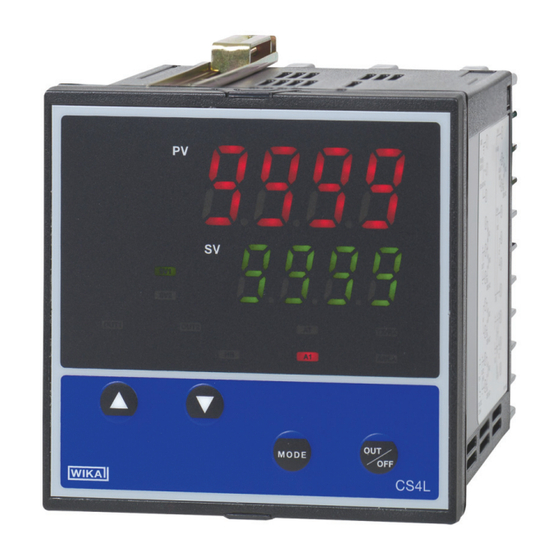
Temperature Indicating Controller, Models CS4H and CS4L
WIKA Operating Instructions CS4H / CS4L
WIKA Alexander Wiegand GmbH & Co. KG
Alexander-Wiegand-Straße 30
63911 Klingenberg/Germany
Phone
(+49) 93 72/132-0
Fax
(+49) 93 72/132-406
info@wika.de
E-Mail
www.wika.de
Operating Instructions
V1.1
07/2006
•
Advertisement
Table of Contents

Subscribe to Our Youtube Channel
Related Manuals for WIKA CS4H


Summary of Contents for WIKA CS4H
- Page 1 Operating Instructions Temperature Indicating Controller, Models CS4H and CS4L WIKA Operating Instructions CS4H / CS4L V1.1 07/2006 • WIKA Alexander Wiegand GmbH & Co. KG Alexander-Wiegand-Straße 30 63911 Klingenberg/Germany Phone (+49) 93 72/132-0 (+49) 93 72/132-406 info@wika.de E-Mail www.wika.de...
- Page 2 • Any unauthorized transfer or copying of this document, in part or in whole, is prohibited. • WIKA is not liable for any damages or secondary damages incurred as a result of using this product, in- cluding any indirect damages.
- Page 3 Operating Instructions Temperature Indicating Controller CS4H / CS4L 1. Installation precautions Caution This instrument is intended to be used under the following environmental conditions (IEC61010-1): Overvoltage category , Pollution degree 2 Mount the controller in a place with: • A minimum of dust, and an absense of corrosive gasses •...
-
Page 4: Table Of Contents
Operating Instructions Temperature Indicating Controller CS4H / CS4L List of contents 1. Model informations 1.1 Model name ····················································································································· 6 1.2 Rated input ······················································································································· 7 2. Name and functions of the sections ········································································ 8 3. Mounting to control panel 3.1 Site selection ·················································································································· 10 3.2 External dimension ·········································································································... - Page 5 Operating Instructions Temperature Indicating Controller CS4H / CS4L A2 action selection ·········································································································· 26 A1 action Energized/Deenergized selection ···································································· 26 A2 action Energized/Deenergized selection ···································································· 26 A1 hysteresis setting ······································································································· 26 A2 hysteresis setting ······································································································· 26 A1 action delayed timer setting ······················································································· 27 A2 action delayed timer setting ·······················································································...
-
Page 6: Model Informations
Operating Instructions Temperature Indicating Controller CS4H / CS4L 1. Model informations 1.1 Model name and order code - 3 A / M - -... Series name CS4_ Model CS4H: W48 x H96 x D100mm CS4L: W96 x H96 x D100mm... -
Page 7: Rated Input
Operating Instructions Temperature Indicating Controller CS4H / CS4L 1.2 Rated input Input type Input range Resolution –200 ... 1370 °C –320 ... 2500 °F 1 °C (°F) –199.9 ... 400.0 °C –199.9 ... 750.0 °F 0.1 °C (°F) –200 ... 1000 °C –320 ... -
Page 8: Name And Functions Of The Sections
Operating Instructions Temperature Indicating Controller CS4H / CS4L 2. Name and functions of the sections (10) (10) (11) (11) (14) (14) (12) (15) (15) (12) (13) (13) (Fig. 2-1) Indications: (1) PV: PV display Indicates the process variable (PV) with a red LED. - Page 9 Operating Instructions Temperature Indicating Controller CS4H / CS4L Keys: ▲ (12) Increase key Increases numeric value of the setting value. ▼ (13) Decrease key Decreases numeric value of the setting value. (14) MODE: Mode key Switches the setting mode and registers the setting value and selected value.
-
Page 10: Mounting To Control Panel
Operating Instructions Temperature Indicating Controller CS4H / CS4L 3. Mounting to control panel 3.1 Site selection This instrument is intended to be used under the following conditions (IEC61010-1): Overvoltage category , Pollution degree 2 Mount the controller in a place with:... -
Page 11: Panel Cutout
Operating Instructions Temperature Indicating Controller CS4H / CS4L 3.3 Panel cutout • CS4H +0.5 n x 48-3 Lateral close mounting, n: Number of units mounted Caution: When lateral close mounting is used for the controller, +0.5 IP66 specification is not fulfilled. -
Page 12: Mounting
Operating Instructions Temperature Indicating Controller CS4H / CS4L 3.5 Mounting (both CS4H and CS4L) Warning As the case is made of resin, do not use excessive force while screwing in the mounting bracket, or the case could be damaged. The torque is approximately 0.12 Nm. -
Page 13: Wiring Connection
Operating Instructions Temperature Indicating Controller CS4H / CS4L 4. Wiring connection Warning Turn the power supply to the instrument off before wiring or checking. Working or touching the terminal with the power switched on may result in Electric Shock causing severe injury or death. -
Page 14: Wiring Connection Example
Operating Instructions Temperature Indicating Controller CS4H / CS4L Caution • The terminal blocks of the CS4H and CS4L are designed to be wired from the left side. The lead wire must be inserted from the left side of the terminal, and fastened with the terminal screw. - Page 15 Operating Instructions Temperature Indicating Controller CS4H / CS4L [Heater burnout alarm output] (1) This alarm is not available for detecting CT input terminal heater current under phase control. (2) Use current transformer (CT) provided, Power source and pass one lead wire of heater circuit into the hole of the CT.
-
Page 16: Setup
Operating Instructions Temperature Indicating Controller CS4H / CS4L 5. Setup For the thermocouple and RTD inputs, the sensor input characters and temperature unit are indicated on the PV display and the input range high limit value is indicated on the SV display for approximately 3 seconds after the power is turned on (Table 5-1). -
Page 17: Setup Flow Chart
Operating Instructions Temperature Indicating Controller CS4H / CS4L 5.1 Setup flow chart MODE Control output OFF Output manipulated PV/SV display mode (Approx. 1s) function [ (*1) variable MODE (Approx. 3s) ▲ ▼ MODE + MODE + MODE (Approx. 3s) [Main setting mode] [Sub setting mode]... - Page 18 Operating Instructions Temperature Indicating Controller CS4H / CS4L ▲ ▼ + MODE (Approx. 3s) [Auxiliary function setting mode2] Sensor selection MODE Scaling high limit setting OUT2 low limit setting A1 action delayed timer set- ting MODE MODE MODE Scaling low limit setting...
-
Page 19: Main Setting Mode
Operating Instructions Temperature Indicating Controller CS4H / CS4L 5.2 Main setting mode If the MODE key is pressed, main setting mode is selected. ▲ ▼ The setting value (numeric value) can be increased or decreased by pressing the key. If the MODE key is pressed, the setting value is registered and the controller will revert to the PV/SV display mode. -
Page 20: Integral Time Setting
Operating Instructions Temperature Indicating Controller CS4H / CS4L Integral time setting [ ] • Sets the integral time. Setting the value to 0 disables the function. (PD action) • Not available when OUT1 is ON/OFF action • Setting range: 0 … 1000 seconds •... -
Page 21: Hb (Heater Burnout Alarm) Setting
Operating Instructions Temperature Indicating Controller CS4H / CS4L HB (Heater burnout alarm) setting [ X.X are indicated in turn.] • Sets the heater current value for Heater burnout alarm. Setting the value to 0.0 disables the function. • Available only when Heater burnout alarm (option) is added •... -
Page 22: Auxiliary Function Setting Mode
Operating Instructions Temperature Indicating Controller CS4H / CS4L 5.4 Auxiliary function setting mode 1 ▼ In the PV/SV display mode, if the MODE key is pressed while the key is being pressed for approx. 3 seconds, Auxiliary function setting mode 1 can be selected. -
Page 23: Data Transfer Rate Selection
• Default: 9600 bps Parity selection [ • Selects the parity of this unit. • Not available when the option Serial interface [CR5] is not applied or when WIKA protocol is selected in the Communication protocol selection • Selection item:... -
Page 24: Auxiliary Function Setting Mode
Operating Instructions Temperature Indicating Controller CS4H / CS4L 5.5 Auxiliary function setting mode 2 ▲ ▼ In the PV/SV display mode, if the MODE key is pressed while the keys are being pressed for approx. 3 seconds, Auxiliary function setting mode 2 can be selected. -
Page 25: Decimal Point Place Selection
Operating Instructions Temperature Indicating Controller CS4H / CS4L Decimal point place selection [ • Selects the decimal point place. • Available only for DC input • Selection item: (No decimal point) (1 digit after the decimal point) (2 digits after the decimal point) (3 digits after the decimal point) •... -
Page 26: Overlap Band/Dead Band Setting
Operating Instructions Temperature Indicating Controller CS4H / CS4L Overlap band/Dead band setting [ • Sets Overlap band/Dead band for OUT1 and OUT2. + setting value: Dead band – setting value: Overlap band • Not available for ON/OFF action or when 2. control output (option) is not added •... -
Page 27: A1 Action Delayed Timer Setting
Operating Instructions Temperature Indicating Controller CS4H / CS4L A1 action delayed timer setting [ • Sets the action delayed timer for A1. When setting time has passed after the input enters the alarm output range, the alarm is acti- vated. - Page 28 Operating Instructions Temperature Indicating Controller CS4H / CS4L [Sensor correction function] This corrects the input value from the sensor. When a sensor cannot be set at a location where control is desired, the sensor measuring temperature may deviate from the temperature in the controlled location.
-
Page 29: Control Output Off Function
Operating Instructions Temperature Indicating Controller CS4H / CS4L 5.6 Control output OFF function Control output OFF function [ • A function to pause the control action or turn the control output of the unused instrument of the plural units OFF even if the power to the instrument is supplied. -
Page 30: Running
After the controller has been mounted to the control panel and wiring is completed, it can be started in the following manner. (1) Turn the power supply to the CS4H, CS4L ON. For thermocouple and RTD inputs, for approx. 3 seconds after the power is switched ON, sensor input character and temperature unit are indicated on the PV display, and the input range high limit value is indicated on the SV display. -
Page 31: Action Explanation
Operating Instructions Temperature Indicating Controller CS4H / CS4L 7. Action explanation 7.1 OUT1 action Heating (reverse) action Cooling (direct) action Proportional band Proportional band Control action SV setting SV setting Cycle action is performed according to deviation. Cycle action is performed according to deviation. -
Page 32: Out1 On/Off Action
Operating Instructions Temperature Indicating Controller CS4H / CS4L 7.3 OUT1 ON/OFF action Heating (reverse) action Cooling (direct) action Hysteresis Hysteresis Control action SV setting SV setting 12V DC 0V DC 0V DC 12V DC 20mA DC 20mA DC 4mA DC... -
Page 33: Out2 (Heating/Cooling Control) Action (Option)
Operating Instructions Temperature Indicating Controller CS4H / CS4L 7.4 OUT2 (Heating/Cooling control) action (option) Heating P-band (Cooling P-band) Control Heaing (Cooling action action action) SV setting Cycle action is performed according to deviation. Cycle action is performed according to deviation. - Page 34 Operating Instructions Temperature Indicating Controller CS4H / CS4L When setting Dead band Heating P-band Dead band (Cooling P-band) Heatng (Cooling Control action action action) SV setting Cycle action is performed according to deviation. Cycle action is performed according to deviation.
- Page 35 Operating Instructions Temperature Indicating Controller CS4H / CS4L When setting Overlap band with Relay contact output. Heating P-band Cooling P-band Overlap band Heating (Cooling Control action action action) SV setting Cycle action is performed according to deviation. Cycle action is performed according to deviation.
-
Page 36: A1 And A2 Actions
Operating Instructions Temperature Indicating Controller CS4H / CS4L 7.5 A1 and A2 actions High limit alarm Low limit alarm A1 hysteresis A1 hysteresis Alarm action + Alarm Alarm Setting Alarm Setting + Alarm set point set point set point set point... -
Page 37: Sv1/Sv2 External Selection Action
Operating Instructions Temperature Indicating Controller CS4H / CS4L High/Low limits alarm with standby A1 hysteresis Alarm action : A1 output terminals between 7 and 8 is ON. : A1 output terminals between 7 and 8 is ON or OFF. SV setting... -
Page 38: Pid Auto-Tuning Of This Controller
Operating Instructions Temperature Indicating Controller CS4H / CS4L 8.2 PID auto-tuning of this controller In order to decide each value of P, I, D and ARW automatically, this system forcibly fluctuates the object being controlled. (1) When the difference between the setting value and processing temperature is large as the temperature rises. -
Page 39: Auto-Reset (Offset Correction)
Operating Instructions Temperature Indicating Controller CS4H / CS4L 8.3 Auto-reset (offset correction) Auto-reset is performed to correct the offset at the point at which PV indication is stabilized within the proportional band during the PD action. Since the corrected value is internally memorized, it is not necessary to perform the auto-reset again as long as the process is the same. -
Page 40: Specifications
Operating Instructions Temperature Indicating Controller CS4H / CS4L 9. Specifications 9.1 Standard specifications Mounting method : Flush Setting method : Membrane sheet key Display CS4H PV display : Red LED 4 digits, character size, 11.2 x 5.4 (H x W) mm SV display : Green LED 4 digits, character size, 11.2 x 5.4 (H x W) mm... - Page 41 Operating Instructions Temperature Indicating Controller CS4H / CS4L Accuracy (Setting, indication) Thermocouple : Within ±0.2 % of input range full scale ±1 digit or within ±2 °C (4 °F), whichever is greater However, R, S inputs, 0 … 200 °C (0 … 400 °F): Within ±6 °C (12 °F) B input, 0 …...
- Page 42 Mass : CS4H (approx. 250 g), CS4L, (approx. 370 g) External dimension : CS4H, 48 x 96 x 100 mm (W x H x D) CS4L, 96 x 96 x 100 mm (W x H x D) Material : Case, Flame resistant resin...
- Page 43 Operating Instructions Temperature Indicating Controller CS4H / CS4L Attached functions [Sensor correction function] [Setting value lock function] [Input burnout indication] • For thermocouple or RTD input, if the input value exceeds the Indication range high limit value, the PV display blinks “...
- Page 44 Operating Instructions Temperature Indicating Controller CS4H / CS4L [Burnout] When the thermocouple or RTD input is burnt out, OUT1 is turned off (for control output Analogue current signal (4 ... 20 mA), OUT1 low limit value) and the PV display blinks “...
-
Page 45: Optional Specifications
Operating Instructions Temperature Indicating Controller CS4H / CS4L 9.2 Optional specifications Alarm output 2 (A2) process value monitoring [option codes: 2AS or 2AL] When A2 action is set as Energized, the alarm action point is set by ±deviation to OUT1 setting (except Process alarm). - Page 46 Receives digital setting value from WIKA programmable controller (with option SVTC). (It is necessary to set the Setting value lock function to Lock 3 for the CS4H and CS4L.) When the data from WIKA programmable controller exceeds SV high limit or SV low limit, the CS4H or CS4L ignores the value, and performs the control with SV high limit or SV low limit.
-
Page 47: Troubleshooting
Operating Instructions Temperature Indicating Controller CS4H / CS4L 10. Troubleshooting If any malfunctions occur, refer to the following items after checking the power of the controller. Warning Turn the power supply to the instrument off before wiring or checking. Working or touching the terminal with the power switched on may result in Electric Shock causing severe injury or death. -
Page 48: Key Operation
Operating Instructions Temperature Indicating Controller CS4H / CS4L Problem Presumed cause and solution The value set during • Is the sensor for DC voltage (0 ... 5 V DC, 0 ... 10 V DC) or DC current the Scaling low limit (0 ... -
Page 49: Control
Operating Instructions Temperature Indicating Controller CS4H / CS4L 10.3 Control Problem Presumed cause and solution Process variable (tem- • The sensor is out of order. perature) does not rise. Replace the sensors. • Is sensor terminal or control output terminal securely mounted to the instrument terminal? Mount them securely. - Page 50 Operating Instructions Temperature Indicating Controller CS4H / CS4L [Auxiliary function setting mode 1] Character Setting item Default value Data Setting value lock selection Unlock SV high limit setting Input range high limit value SV low limit setting Input range low limit value Sensor correction setting 0.0 °C...
Need help?
Do you have a question about the CS4H and is the answer not in the manual?
Questions and answers