Advertisement
Quick Links
Advertisement

Related Manuals for ARC FLEXEPH


Summary of Contents for ARC FLEXEPH
- Page 1 FLEXEPH Instruction Manual...
- Page 2 Service Information Your New Radio Remote Control System Thank you for your purchase of ARC Flex EPH radio remote control system. Without a doubt, our Flex EPH system is the ultimate solution for providing precise, undeterred, and safe control of your material.
- Page 3 It is the responsibility of the owners, users and operators of the ARC Products to know, understand and follow all of these requirements. It is the responsibility of the employer to make its employees aware of all of the above listed requirements and to make certain that all operators are properly trained.
- Page 4 Reorient or relocate the receiving antenna. Increase the separation between the equipment and receiver. Connect the equipment into an outlet on a circuit different from that to which the receiver is connected. Consult the dealer or an experienced radio/TV technician for help. ...
-
Page 5: Table Of Contents
Table of Contents Page Introduction Radio Controlled Safety General System Information Transmitter 3.1.1 8EPH External Illustration 3.1.2 12EPH External Illustration 3.1.3 8EPH Internal Illustration 3.1.4 12EPH Internal Illustration Receiver 3.2.1 8EPH and 12EPH External Illustration 3.2.2 8EPH and 12EPH Internal Illustration Function Settings Transmitter 4.1.1... -
Page 6: Introduction
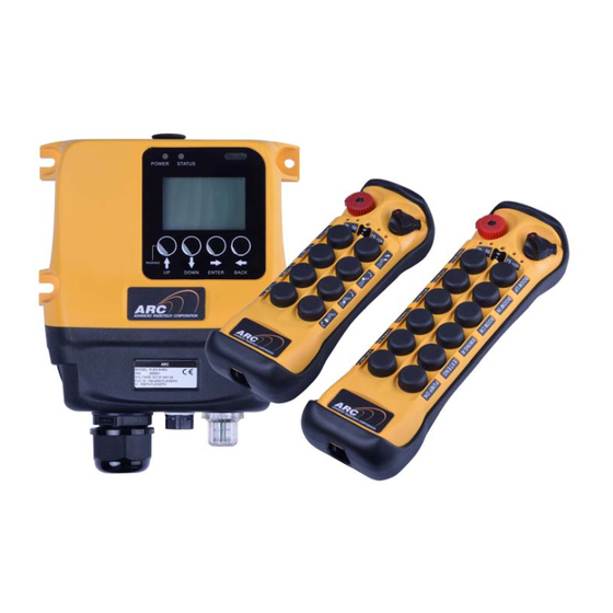
1. Introduction The Flex EPH radio remote control system is designed for control of industrial hydraulic equipment with PWM and Current outputs. Each Flex EPH system consists of a transmitter handset and a receiver unit. Other standard- equipped accessories include transmitter waist belt, vinyl pouch, pushbutton labels, output cable and instruction manual CD. -
Page 7: Radio Controlled Safety
2. Radio Controlled Safety WARNINGS and CAUTIONS Throughout this document WARNING and CAUTION statements have been deliberately placed to highlight items critical to the protection of personnel and equipment. WARNING – A warning highlights an essential operating or maintenance procedure, practice, etc. which if not strictly observed, could result in injury or death of personnel, or long term physical hazards. - Page 8 2.1 CRITICAL INSTALLATION CONSIDERATIONS WARNING PRIOR TO INSTALLATION AND OPERATION OF THIS EQUIPMENT, READ AND DEVELOP AN UNDERSTANDING OF THE CONTENTS OF THIS MANUAL AND THE OPERATION MANUAL OF THE EQUIPMENT OR DEVICE TO WHICH THIS EQUIPMENT WILL BE INTERFACED. FAILURE TO FOLLOW THIS WARNING COULD RESULT IN SERIOUS INJURY OR DEATH AND DAMAGE TO EQUIPMENT.
- Page 9 2.4 SAFETY INFORMATION AND RECOMMENDED TRAINING FOR RADIO CONTROLLED EQUIPMENT OPERATORS Anyone being trained to operate radio controlled equipment should possess as a minimum the following knowledge and skills before using the radio-controlled equipment. The operator should: have knowledge of hazards pertaining to equipment operation ...
- Page 10 TAKEN OUT OF SERVICE AND BE REPORTED TO THE SUPERVISOR. DAMAGED AND INOPERABLE RADIO CONTROLLER EQUIPMENT SHOULD BE RETURNED TO ARC FOR EVALUATION AND REPAIR. FAILURE TO FOLLOW THIS WARNING COULD RESULT IN SERIOUS INJURY OR DEATH AND DAMAGE TO EQUIPMENT.
- Page 11 2.8 USED SYMBOL DESCRIPTION Danger electric shock risk Equipment Recycling: The production and operation of this equipment requires the recycling and utilization of natural resources. There are substances that are harmful to the environment or human health. To avoid the release of such substances into the environment and to reduce the use of natural resources, it is recommended that you recycle this product through a suitable system to ensure that most of the materials are properly recycled or reused.
-
Page 12: General System Information
3. General System Information 3.1 Transmitter 3.1.1 8EPH External Illustration STOP Button Pushbutton 6 (PB6) Power Key Switch Pushbutton 7 (PB7) Status LED Indicator Pushbutton 8 (PB8) Pushbutton 1 (PB1) TAC* and Wireless Charging Slot Pushbutton 2 (PB2) Battery Cover Screw Pushbutton 3 (PB3) System Information Pushbutton 4 (PB4) -
Page 13: 12Eph External Illustration
3.1.2 12EPH External Illustration STOP Button Pushbutton 8 (PB8) Power Key Switch Pushbutton 9 (PB9) Status LED Indicator Pushbutton 10 (PB10) Pushbutton 1 (PB1) Pushbutton 11 (PB11) Pushbutton 2 (PB2) Pushbutton 12 (PB12) Pushbutton 3 (PB3) TAC* and Wireless Charging Slot Pushbutton 4 (PB4) Battery Cover Screw Pushbutton 5 (PB5) -
Page 14: 8Eph Internal Illustration
3.1.3 8EPV Internal Illustration RF Transceiver Board 25/50/75/100% LED Indicators Encoder Board Function Dipswitch Status LED Indicator Programming Port Infrared Sensors Flex EPH Instruction Manual January 2021 v1.0 Page 13 of 71... -
Page 15: 12Eph Internal Illustration
3.1.4 12EPV Internal Illustration RF Transceiver Board 25/50/75/100% LED Indicators Encoder Board Function Dipswitch Status LED Indicator Programming Port Infrared Sensors Flex EPH Instruction Manual January 2021 v1.0 Page 14 of 71... -
Page 16: Receiver
3.2 Receiver 3.2.1 8EPV and 12EPV External Illustration External Antenna Port (optional) System Information Power LED Indicator Cord Grip Status LED Indicator Infrared Sensors LCD Screen Goretex Vent Remote Pairing and Mounting Bracket (optional) Programming Buttons Flex EPH Instruction Manual January 2021 v1.0 Page 15 of 71... -
Page 17: 8Eph And 12Eph Internal Illustration
3.2.2 8EPV and 12EPV Internal Illustration Power and Status LED Indicators Infrared Sensors RF Transceiver Board LCD Screen CAN Bus Connector Remote Pairing and Programming Buttons Flex EPH Instruction Manual January 2021 v1.0 Page 16 of 71... -
Page 18: Function Settings
4. Function Settings 4.1 Transmitter 4.1.1 Transmitter Firmware Version 1) Rotate the power switch key to OFF ( 0 ) position. 2) With the STOP button elevated, press and hold PB1 and PB3 at the same time. 3) Rotate the power switch key to ON ( I ) position. 4) Let go PB1 and PB3 at the same time. - Page 19 B. Assigned Channel Scheme (preset system channel) Both transmitter and receiver is assigned with a matching preset channel (channel 01~62). Pitch & Catch configuration “must” set to assigned channel scheme. 1) Rotate the power switch key to OFF ( 0 ) position. 2) With the STOP button elevated, press and hold PB1 and PB2 at the same time.
-
Page 20: Remote Pairing
4.1.3 Remote Pairing A. Transmitter-to-Transmitter Pairing: 1) Rotate the power switch key to OFF ( 0 ) position. 2) With the STOP button elevated, press and hold PB1 and PB3 at the same time. 3) Rotate the power switch key to ON ( I ) position. 4) Let go PB1 and PB3 at the same time (entered Remote Pairing mode). -
Page 21: Transmitter Start Function Settings
C. Transmitter-to-Receiver Pairing: JP8 Open Method: After the transmitter enters the Remote Pairing mode, output transmitter data by press and hold PB4 on the transmitter and receive data by press and hold the PAIRING button on the receiver cover, both at the same time. When the transmitter Status LED turns to constant green while both pushbuttons are still pressed down the pairing is completed. -
Page 22: Infrared Programming
Other custom functions and settings not listed in this manual can be programmed via the infrared IR programmer unit, such as the system serial number, frequency range, TAC, new and updated functions, and many others. Please contact ARC representative for more details. Flex EPH Instruction Manual January 2021 v1.0... -
Page 23: Transmitter Access Card (Tac) Settings
4.1.8 Transmitter Access Card (TAC) Settings Follow the instruction below on how to program the TAC into the transmitter. The infrared IR programmer unit is required to complete the programming. Please contact ARC representative for more details. 1) Rotate the power switch key to OFF ( 0 ) position. -
Page 24: Display Frequency Band
6) Exit Frequency Band Display mode by rotate the power switch key to OFF ( 0 ) position. 4.1.10 Infrared Function Settings The transmitter is embedded with infrared sensors for infrared start function. These settings require using the infrared IR programmer unit. Please contact ARC representative for more details. 4.1.11 Zero-G Sensor Settings The transmitter is embedded with a Zero-G sensor to guard against any unintended control of the crane or equipment when transmitter is thrown or dropped. -
Page 25: Receiver
(wire #10). There are other types of auxiliary functions made available for Function 1 output. Refer to section 4.2.4 and section 4.2.5.6 ~ 4.2.5.8 Function outputs descriptions and programming. Please contact ARC representative if your application requires other types of auxiliary function connected to these Function output relays. - Page 26 4.2.1.5 Momentary Contact When pushbutton is released the corresponding output relay will open or deactivate. This type of relay action usually applies to external applications such as horn and buzzer. Refer to section 4.2.2.2 and section 4.2.5.9 ~ 4.2.5.14 output relay descriptions and programming.
-
Page 27: Output Programming
4.2.2 Output Programming 4.2.2.1 Interlocked Digital Outputs Interlocked means any pushbutton pair can not be pressed simultaneously as it will cancel each other out. Refer to section 4.2.1 and section 4.2.5.9 ~ 4.2.5.14 output descriptions and programming. Function # Function Descriptions (left button / right button) 00000000 Interlocking single speed 00001100... - Page 28 4.2.2.2 Non-interlocked Digital Outputs Non-interlocked setting allows the pushbutton pair be pressed simultaneously. It usually applies to equipment’s auxiliary functions such as lights, horn or buzzer. Refer to section 4.2.1 and section 4.2.5.9 ~ 4.2.5.14 output descriptions and programming. Function # Function Descriptions (left button / right button) 10000000 Normal / Normal...
-
Page 29: Jumper Functions
4.2.3 Jumper Functions Refer to section 4.2.5.28 jumper function programming. Jumper Settings Function For system testing only (receiver MAIN-A relay disabled) (Short) Receiver-to-transmitter remote pairing (Open) (pressing the Pairing button required) Receiver-to-transmitter remote pairing (Short) (pressing the Pairing button not required) 4.2.4 Function Outputs Listed below are other types of functions that can be outputted through the three Function outputs (wire #10, wire #11 and CN8). -
Page 30: Programming
4.2.5 Programming 1) Turn on the receiver power (receiver in standby mode). STATUS STANDBY 02:--- 1:--- 04:--- 3:--- 06:--- 5:--- 08:--- 7:--- 10:--- 9:--- 12:--- 11:--- 2) Press and hold both ENTER and BACK buttons for up to 3 seconds to enter system programming. - Page 31 4.2.5.1 System Serial Number (S/N) For safety measure, system serial number can only be changed via the IR programmer unit. Please contact ARC representative for more details. Press the UP/DOWN buttons to scroll through other system settings >S/N : 000001...
- Page 32 4.2.5.4 System Channel Programming (CHANNEL) : 000001 TYPE : 000 FREQ : 433.050 >CHANNEL: UNASSIGN CH SCAN: 01 1) Press the ENTER button to enter System Channel Programming (cursor shown next to UNASSIGN* or the 2-digit channel value**). 2) Press the UP/DOWN buttons to scroll and select UNASSIGN or channel value as a whole (channel 1~62).
- Page 33 4.2.5.6 Function-1 Programming (OUT 5 / wire #10) Please refe to section 4.2.4 for various types of function outputs available. >FUNC1 : NORMAL FUNC1 :>NORMAL 1) Press the ENTER button to enter Function-1 Programming (cursor shown next to NORMAL or other setting previously programmed). 2) Press the ENTER button again to change setting.
- Page 34 PWM Output 1) Select PWM for PWM output. FUNC1 : ID FUNC1 : ID >PWM >000-100% RAMP ACC 0.0S DEC 0.0S 2) Press the UP/DOWN buttons to select the PWM % value. 3) Press the ENTER button and then the UP/DOWN buttons to change % value on the far left.
- Page 35 4.2.5.7 Function-2 Programming (OUT 6 / wire #11) Please refe to section 4.2.4 for various types of function outputs available. >FUNC2 : NORMAL FUNC2 :>NORMAL 1) Press the ENTER button to enter Function-2 Programming (cursor shown next to NORMAL or other setting previously programmed). 2) Press the ENTER button again to change setting.
- Page 36 PWM Output 1) Select PWM for PWM output. FUNC2 : ID FUNC2 : ID >PWM >000-100% RAMP ACC 0.0S DEC 0.0S 2) Press the UP/DOWN buttons to select the PWM % value. 3) Press the ENTER button and then the UP/DOWN buttons to change % value on the far left.
- Page 37 4.2.5.9 PB1 & PB2 Programming Digital Output Please refe to section 4.2.2.1 and 4.2.2.2 Interlocked and Non-interlocked digital output variants and function number (8 digits). PB1&PB2 PB1&PB2 : >DIGITAL : DIGITAL 10000000 >10000000 1) Press the ENTER button to enter PB1 & PB2 Programming (cursor shown next to DIGITAL or ANALOG).
- Page 38 4.2.5.10 PB3 & PB4 Programming Digital Output Please refe to section 4.2.2.1 and 4.2.2.2 Interlocked and Non-interlocked digital output variants and function number (8 digits). PB3&PB4 PB3&PB4 : >DIGITAL : DIGITAL 10000000 >10000000 1) Press the ENTER button to enter PB3 & PB4 Programming (cursor shown next to DIGITAL or ANALOG).
- Page 39 4.2.5.11 PB5 & PB6 Programming Digital Output Please refe to section 4.2.2.1 and 4.2.2.2 Interlocked and Non-interlocked digital output variants and function number (8 digits). PB5&PB6 PB5&PB6 : >DIGITAL : DIGITAL 10000000 >10000000 1) Press the ENTER button to enter PB5 & PB6 Programming (cursor shown next to DIGITAL or ANALOG).
- Page 40 4.2.5.12 PB7 & PB8 Programming Digital Output Please refe to section 4.2.2.1 and 4.2.2.2 Interlocked and Non-interlocked digital output variants and function number (8 digits). PB7&PB8 PB7&PB8 : >DIGITAL : DIGITAL 10000000 >10000000 1) Press the ENTER button to enter PB7 & PB8 Programming (cursor shown next to DIGITAL or ANALOG).
- Page 41 4.2.5.13 PB9 & PB10 Programming Digital Output Please refe to section 4.2.2.1 and 4.2.2.2 Interlocked and Non-interlocked digital output variants and function number (8 digits). PB9&PB10 PB9&PB10 : >DIGITAL : DIGITAL 10000000 >10000000 1) Press the ENTER button to enter PB9 & PB10 Programming (cursor shown next to DIGITAL or ANALOG).
- Page 42 4.2.5.14 PB11 & PB12 Programming Digital Output Please refe to section 4.2.2.1 and 4.2.2.2 Interlocked and Non-interlocked digital output variants and function number (8 digits). PB11&PB12 PB11&PB12 : >DIGITAL : DIGITAL 10000000 >10000000 1) Press the ENTER button to enter PB11 & PB12 Programming (cursor shown next to DIGITAL or ANALOG).
- Page 43 4.2.5.15 PB1 Analog Output Programming Program this section if PB1 & PB2 Programming on section 4.2.5.9 is set to ANALOG. This section will not shown if section 4.2.5.9 is set to set to DIGITAL. Current Output >PB1 ANALOG PB1 ANALOG : CURRENT :>CURRENT 0000-3000mA...
- Page 44 4.2.5.16 PB2 Analog Output Programming Program this section if PB1 & PB2 Programming on section 4.2.5.9 is set to ANALOG. This section will not shown if section 4.2.5.9 is set to set to DIGITAL. Current Output >PB2 ANALOG PB2 ANALOG : CURRENT :>CURRENT 0000-3000mA...
- Page 45 4.2.5.17 PB3 Analog Output Programming Program this section if PB3 & PB4 Programming on section 4.2.5.10 is set to ANALOG. This section will not shown if section 4.2.5.10 is set to set to DIGITAL. Current Output >PB3 ANALOG PB3 ANALOG : CURRENT :>CURRENT 0000-3000mA...
- Page 46 4.2.5.18 PB4 Analog Output Programming Program this section if PB3 & PB4 Programming on section 4.2.5.10 is set to ANALOG. This section will not shown if section 4.2.5.10 is set to set to DIGITAL. Current Output >PB4 ANALOG PB4 ANALOG : CURRENT :>CURRENT 0000-3000mA...
- Page 47 4.2.5.19 PB5 Analog Output Programming Program this section if PB5 & PB6 Programming on section 4.2.5.11 is set to ANALOG. This section will not shown if section 4.2.5.11 is set to set to DIGITAL. Current Output >PB5 ANALOG PB5 ANALOG : CURRENT :>CURRENT 0000-3000mA...
- Page 48 4.2.5.20 PB6 Analog Output Programming Program this section if PB5 & PB6 Programming on section 4.2.5.11 is set to ANALOG. This section will not shown if section 4.2.5.11 is set to set to DIGITAL. Current Output >PB6 ANALOG PB6 ANALOG : CURRENT :>CURRENT 0000-3000mA...
- Page 49 4.2.5.21 PB7 Analog Output Programming Program this section if PB7 & PB8 Programming on section 4.2.5.12 is set to ANALOG. This section will not shown if section 4.2.5.12 is set to set to DIGITAL. Current Output >PB7 ANALOG PB7 ANALOG : CURRENT :>CURRENT 0000-3000mA...
- Page 50 4.2.5.22 PB8 Analog Output Programming Program this section if PB7 & PB8 Programming on section 4.2.5.12 is set to ANALOG. This section will not shown if section 4.2.5.12 is set to set to DIGITAL. Current Output >PB8 ANALOG PB8 ANALOG : CURRENT :>CURRENT 0000-3000mA...
- Page 51 4.2.5.23 PB9 Analog Output Programming Program this section if PB9 & PB10 Programming on section 4.2.5.13 is set to ANALOG. This section will not shown if section 4.2.5.13 is set to set to DIGITAL. Current Output >PB9 ANALOG PB9 ANALOG : CURRENT :>CURRENT 0000-3000mA...
- Page 52 4.2.5.24 PB10 Analog Output Programming Program this section if PB9 & PB10 Programming on section 4.2.5.13 is set to ANALOG. This section will not shown if section 4.2.5.13 is set to set to DIGITAL. Current Output >PB10 ANALOG PB10 ANALOG : CURRENT :>CURRENT 0000-3000mA...
- Page 53 4.2.5.25 PB11 Analog Output Programming Program this section if PB11 & PB12 Programming on section 4.2.5.14 is set to ANALOG. This section will not shown if section 4.2.5.14 is set to set to DIGITAL. Current Output >PB11 ANALOG PB11 ANALOG : CURRENT :>CURRENT 0000-3000mA...
- Page 54 4.2.5.26 PB12 Analog Output Programming Program this section if PB11 & PB12 Programming on section 4.2.5.14 is set to ANALOG. This section will not shown if section 4.2.5.14 is set to set to DIGITAL. Current Output >PB12 ANALOG PB12 ANALOG : CURRENT :>CURRENT 0000-3000mA...
- Page 55 4.2.5.27 Output Frequency Programming >OUT FREQ OUT FREQ : 0100Hz : >0100Hz 1) Press the ENTER button to enter Output Frequency Programming (cursor shown next to 0100Hz or other setting previously programmed ). 2) Press the UP/DOWN buttons to scroll and select the required value (100Hz~1,000Hz). 3) Press the BACK button to go back to Output Frequency Programming (cursor shown next to OUT FREQ).
-
Page 56: Indicator Light And Buzzer Installation
Make sure the indicator light or the buzzer is connected to the Function-3 CN8 port inside the receiver. Please contact ARC representative if you would like the indicator light or the buzzer work differently than described above. Refer to section 4.2.4 and section 4.2.5.6 ~ 4.2.5.8 Function relay descriptions and programming... -
Page 57: System Channels Table
4.2.7 System Channels Table 433~439MHz: Primary/Secondary Primary/Secondary Channel Channel Frequency Frequency 433.050/436.550 434.600/438.100 433.100/436.600 434.650/438.150 433.150/436.650 434.700/438.200 433.200/436.700 434.750/438.250 433.250/436.750 434.800/438.300 433.300/436.800 434.850/438.350 433.350/436.850 434.900/438.400 433.400/436.900 434.950/438.450 433.450/436.950 435.000/438.500 433.500/437.000 435.050/438.550 433.550/437.050 435.100/438.600 433.600/437.100 435.150/438.650 433.650/437.150 435.200/438.700 433.700/437.200 435.250/438.750 433.750/437.250 435.300/438.800 433.800/437.300 435.350/438.850... - Page 58 863~869MHz: Primary/Secondary Primary/Secondary Channel Channel Frequency Frequency 863.050/866.550 864.600/868.100 863.100/866.600 864.650/868.150 863.150/866.650 864.700/868.200 863.200/866.700 864.750/868.250 863.250/866.750 864.800/868.300 863.300/866.800 864.850/868.350 863.350/866.850 864.900/868.400 863.400/866.900 864.950/868.450 863.450/866.950 865.000/868.500 863.500/867.000 865.050/868.550 863.550/867.050 865.100/868.600 863.600/867.100 865.150/868.650 863.650/867.150 865.200/868.700 863.700/867.200 865.250/868.750 863.750/867.250 865.300/868.800 863.800/867.300 865.350/868.850 863.850/867.350 865.400/868.900 863.900/867.400 865.450/868.950...
- Page 59 921~927MHz: Primary/Secondary Primary/Secondary Channel Channel Frequency Frequency 921.000/924.500 922.550/926.050 921.050/924.550 922.600/926.100 921.100/924.600 922.650/926.150 921.150/924.650 922.700/926.200 921.200/924.700 922.750/926.250 921.250/924.750 922.800/926.300 921.300/924.800 922.850/926.350 921.350/924.850 922.900/926.400 921.400/924.900 922.950/926.450 921.450/924.950 923.000/926.500 921.500/925.000 923.050/926.550 921.550/925.050 923.100/926.600 921.600/925.100 923.150/926.650 921.650/925.150 923.200/926.700 921.700/925.200 923.250/926.750 921.750/925.250 923.300/926.800 921.800/925.300 923.350/926.850 921.850/925.350 923.400/926.900...
-
Page 60: Receiver Installation
5. Receiver Installation 5.1 Wiring Diagram Flex 8EPH Model * COM-1 and COM-2 input voltage range: DC 12~24V. * Transmitter equipped with A/B/A+B rotary switch on PB8 position: Connect A output to wire #17 and B output to wire #18. Flex EPH Instruction Manual January 2021 v1.0 Page 59 of 71... - Page 61 Flex 12EPH Model * COM-1 and COM-2 input voltage range: DC 12~24V. * Transmitter equipped with A/B/A+B rotary switch on PB12 position: Connect A output to wire #17 and B output to wire #18. Flex EPH Instruction Manual January 2021 v1.0 Page 60 of 71...
-
Page 62: Pre-Installation Precautions
5.2 Pre-installation Precautions 1. Make sure the transmitter and receiver are with identical serial number and channel. 2. Make sure the receiver is not set to the same channel as any other systems in use in the surrounding area. 3. Make sure the equipment is working properly prior to installation. 4. - Page 63 4. When installing an external antenna, make sure the MCX jack located on the decoder board inside the receiver is connected and antenna setting set to EXT (refer to section 4.2.5.29). 5. For better reception, make sure the receiver is in an upright position. 6.
- Page 64 1. Drill two holes on the control panel, wall or location where the receiver is to be installed. Ø4.8 mm (Ø0.19") 2. Slide down the receiver along the guided track to secure the receiver to the mounting bracket. 3. Remove the receiver by pressing down the bracket release and pull the receiver upward until it clears the guided track.
-
Page 65: Operating Procedures
6. Operating Procedures 6.1 General Operation Reset the STOP button located on the top left-hand corner of the transmitter by rotating it clockwise or counter clockwise, the button will pop up. Turn on the transmitter power by inserting the power switch key and rotate to ON ( I ) position. →... -
Page 66: Pushbutton Output Resolution Adjustments
execute the START command to reconnect the receiver MAIN relays. For safety, executing the START command is strictly required every time when the transmitter is turned on or after every STOP button reset. After 5 or 30 minutes of inactivity (pushbutton not pressed), the receiver MAIN relays are temporarily disconnected (refer to section 4.1.5 Inactivity Timer Settings). -
Page 67: Transmitter Access Card (Tac) Operation
6.4 Transmitter Access Card (TAC) Operation After turning on the transmitter power, place the TAC directly over the RFID marking located on the backside of the transmitter. A 2-second green on the Status LED represents access card accepted. Status LED with red blinks represents invalid access card. -
Page 68: System Status Indications
6.7 System Status Indications 6.7.1 Transmitter Status LED Indications Type Display Type Indication Voltage below 1.8V at initial power on or Constant red during operation Voltage below 1.75V during operation Constant red → off (receiver MAIN relays shut off) Voltage below 1.85V during operation 1 red blink followed by a 2-second pause (change batteries suggested) - Page 69 6.7.2 Receiver Status LED Indications Type Display Type (Green & Red) Indication Fast green blinks Decoding in process Slow green blinks Decoding on standby 2 red blinks Receiver MAIN relays jammed or defective 3 red blinks Decoding processors defective 4 red blinks Receiving RF board defective Fast red blinks Incorrect transmitter serial number...
- Page 70 6.7.5 Receiver Status LCD Indications STATUS STATUS Decoding DECODING STANDBY on standby 02:--- 1:--- 02:--- 1:--- 04:--- 3:--- 04:--- 3:--- Decoding Transmitter 06:--- 5:--- in progress 06:--- 5:--- timeout 08:--- 7:--- 08:--- 7:--- Stop button 10:--- 9:--- 10:--- 9:--- pressed down 12:--- 11:--- 12:---...
-
Page 71: General Specifications
7. General Specifications Frequency Range 433.050MHz ~ 439.600MHz 863.050MHz ~ 869.600MHz 921.000MHz ~ 927.550MHz Number of Channels 62 channels Channel Spacing 50 KHz Modulation Digital Frequency Modulation based on Manchester Code, 20bit address, 32bit CRC and Hamming Code. Encoder & Decoder Microprocessor-controlled Transmitting Range >100 Meters (300 feet) -
Page 72: Eu Declaration Of Conformity
EU Declaration of Conformity (RED, LVD & Machinery) For the following equipment: Product Flex EPH Series Radio Remote Control System Multiple Listee Model No. Flex 8EPH and 12EPH Manufacturer’s Name Advanced Radiotech Corporation Manufacturer’s Address No.3, South 1 Road, Chien Chen District, Kaohsiung, Taiwan We hereby declare, that all major safety requirements, concerning the CE Mark Machinery Directive 2006/42/EC, Low Voltage Directive 2014/35/EU (LVD) and Radio...
Need help?
Do you have a question about the FLEXEPH and is the answer not in the manual?
Questions and answers