iOptron CEM70G Instruction Manual
Center-balanced equatorial mount
Hide thumbs
Also See for CEM70G:
- Instruction manual (64 pages) ,
- Quick start manual (7 pages) ,
- Quick start manual (6 pages)

Related Manuals for iOptron CEM70G


Summary of Contents for iOptron CEM70G
- Page 1 ® iOptron CEM70 Center-Balanced Equatorial Mount Instruction Manual Product CEM70(#C70A), CEM70G(#C70AG) and CEM70EC(#C704A0)
- Page 2 Any worm system damage due to improper operation will not be covered by iOptron’s limited warranty. If you have any questions please contact us at support@ioptron.com WARNING! NEVER USE A TELESCOPE TO LOOK AT THE SUN WITHOUT A PROPER FILTER! Looking at or near the Sun will cause instant and irreversible damage to your eye.
-
Page 3: Table Of Contents
Table of Contents Table of Contents ............................3 1. CEM70 Introduction ..........................5 2. CEM70 Terms ............................6 2.1. Parts List ............................6 2.2. Identification of Parts ........................7 2.3. CEM70 Mount Ports .........................7 ® 2.4. Go2Nova 8407+ Hand Controller ....................10 2.4.1. Key Description ........................10 2.4.2. - Page 4 ® Appendix H. Go2Nova Star List ......................55 IOPTRON TWO YEAR TELESCOPE, MOUNT, AND CONTROLLER WARRANTY ......64 Ver. 2.0 2020.12 iOptron reserves the rights to revise this instruction without notice. Actual color/contents/design/function may differ from those described in this instruction manual.
-
Page 5: Cem70 Introduction
The CEM70's performance is demonstrated by its low periodic tracking error: <±3.5 arc seconds for CEM70 and CEM70G, and <0.3 arcsec RMS for CEM70EC. Along with the stability aspect, the CEM70 features an advanced cable management system consisting of more ports in more locations preventing tangle ups and reducing the chance of fractured cables. -
Page 6: Cem70 Terms
SHIPPING CONTENTS Your new CEM70 mount comes in two shipping boxes. One box contains a CEM70 (#C70A), CEM70G (#C70AG) or CEM70EC(#C704A0) mount head, counterweight shaft, hand controller, and accessories. The other box contains one 21lb (9.5kg) counterweight (#7226). The contents are: ... -
Page 7: Identification Of Parts
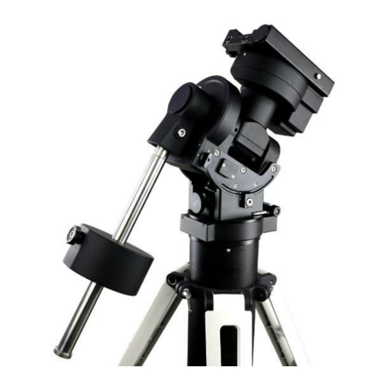
Figure 1.CEM70 mount assembly 2.3. CEM70 Mount Ports CEM70G On Mount Base Main Panel: The main cable connection ports of a CEM70G are shown in Figure 2: Figure 3. ST-4 port wiring Figure 2. Ports on a CEM70G mount base ... - Page 8 On Dovetail Saddle Front Panel (Figure 4a) Shown in Figure 4 are the ports on dovetail saddle of a CEM70G. (a) Front (b) Back Figure 4. Ports on CEM70G dovetail saddle iPORT: Auxiliary port for connecting to other iOptron accessories, such as an electronic focuser or for observatory dome control.
- Page 9 Figure 7. Ports on CEM70 dovetail saddle iPORT: Auxiliary port for connecting to other iOptron accessories, such as an electronic focuser or for observatory dome control. DO NOT plug ST-4 guiding camera cable into this port. It will damage the guide camera electronics.
-
Page 10: Go2Nova 8407+ Hand Controller
® 2.4. Go2Nova 8407+ Hand Controller DEC+ R.A.- R.A.+ DEC- Serial Port Port ® Figure 9. Go2Nova 8407+ hand controller ® The Go2Nova 8407+ hand controller (HC) shown in Figure 9 is the standard controller used on the CEM70 mount. It has an integrated heater that ensures the LCD display will work at the temperature as low as -20ºC (-4ºF). -
Page 11: The Lcd Screen
Serial port: connect the HC to a computer via a RS232 to 4P4C RJ9 cable. The pin-out of the serial port is shown in Figure 10. Figure 10. Serial port pin-out on an 8407+ hand controller 2.4.2. The LCD Screen The 8407+ HC has a large 8-line, 21-character per line, LCD screen which displays information on the status of the mount as shown in Figure 11.The user interface is simple and easy to operate. -
Page 12: Check The Battery
Slew: mount is moving with an arrow key is pressed or a GOTO command, such as “Select and Slew” or “Goto Zero Position”; Tracking: mount is at a tracking status. 10. GPS status: “GPS ON” indicates the mount is connected to its GPS receiver and is seeking a satellite signal. -
Page 13: Cem70 Mount Assembly
Figure 12. Remove the mount STEP 2. Attach the mount The mount has a 152mm base, which can be mounted onto an iOptron Tri-pier, LiteRoc tripod (light payload), or your own tripod/pier with two M8 threaded mounting holes separated 130mm in diameter. - Page 14 STEP 3. Adjust Altitude This step requires you to know the latitude of your current location. This can be found from your 8407+ hand controller after the embedded GPS receives the signal from the satellites. It can also be easily found on the Internet, using a GPS satellite-navigation system, or a GPS capable cell phone. You will have to change this latitude setting every time you significantly change your night sky viewing location.
- Page 15 Shaft locking screw Low latitude set screw Shaft position screw Figure 20. Tilt the counterweight shaft for low Figure 19. Screws for CW shaft tilting altitude DO NOT rock the counterweight shaft rigorously. It may damage the worm system. STEP 5. Install the Counterweight(s) and Telescope Before putting on CW, make sure the mount is at its zero position, i.e., CW shaft points to the ground.
- Page 16 8407+ Hand Controller to the HBX port on the mount base panel. Figure 23. CEM70G (left) and CEM70/EC (right) mount base panel For a CEM70G mount, connect USB3.0 port a computer for computer control, iPolar, iGuider and 3X USB port hub connection.
- Page 17 STEP 8. Setup Hand Controller The CEM70 mount is equipped with a GPS receiver which will receive the UTC time, longitude and latitude information for your current location from satellites after a link is established. However, there are still some parameters need to be entered to reflect your location, such as time zone information and whether daylight saving time is currently in effect.
- Page 18 Position. Loosen the DEC and R.A. Gear Switches in turn to adjust the mount to the Zero Position. Engage the clutches after each adjustment. STEP 10. Polar Alignment In order for an equatorial mount to track properly, it has to be accurately polar aligned. CEM70G and CEM70 are equipped with an iPolar electronic polar.
- Page 19 For CEM70G, plug a USB cable into the USB3.0 port on the mount base panel to connect the iPolar to a computer. Figure 24. Connect CEM70G iPolar to a computer For CEM70/CEM70EC, plug a USB cable into the iPolar port on the rear end of mount RA axisto connect the iPolar to a computer.
- Page 20 NOTE: The movement of the alignment star in your eyepiece may not be perpendicular but crossed, depends on its location in the sky. STEP 9. Put the mount back into the package/carrying case It is recommended to return the mount to Zero Position at the end of the observing session. Lay the mount into the carrying case.
-
Page 21: Getting Started
4. Getting Started ® In order to experience the full GOTO capability of GOTONOVA technology it is very important to set up the mount correctly before observation. 4.1. Setting the Mount and Performing Polar Alignment Assemble your CEM70 mount. Make sure the mount is leveled. Mount an OTA and accessories, and carefully balance the mount on both R.A. -
Page 22: Power-Down Memorization
GOTO function. Press the Help(?) key to identify the star that the telescope is pointing to, as well as nearby bright stars if there is any. 4.6. Power-Down Memorization The CEM70 mount can memorize its R.A. and DEC positions if the mount loses its power by accident, even during high speed slewing. -
Page 23: Complete Functions Of Go2Nova 8407+ Hand Controller
® 5. Complete Functions of Go2Nova 8407+ Hand Controller 5.1. Select and Slew Press MENU => “Select and Slew.” Select an object that you would like to observe and press the ENTER key. ® 8407+ hand controller has a database of over 212,000 objects. Use the ► or ◄ The Go2Nova buttons to move the cursor. -
Page 24: Customer R.a. And Dec
5.1.8. Customer R.A. and DEC Here you can go to a target by entering its R.A. and DEC coordinates. 5.2. Sync to Target This operation will match the telescope's current coordinates to the Target Right Ascension and Declination. It can be used to correct GOTO pointing error. After slewing to an object, press MENU - then scroll to “Sync to Target”... -
Page 25: Three Star Alignment
After the two-star alignment, the altitude and azimuth errors will be displayed. This number can be used to fine tune the polar alignment. For example, if the screen shows 7.5" low and 4.3" east, it means that THE MOUNT axis is pointing low and to the east of the Celestial Pole. -
Page 26: Settings
5.4. Settings 5.4.1. Set Time and Site Refer to STEP 8 in Section 3. 5.4.2. Beep Settings The Hand Controller allows a user to turn off the beep partially, or even go to a silent mode. To change this setting press “MENU =>Settings =>Beep Settings”, Set Up Time and Site Beep Settings Display Settings... -
Page 27: Set Tracking Rate
±0.10X to ±0.99X sidereal rate. Follow the instructions of your autoguiding software for detailed guiding operation. CEM70G has an integrated guiding camera iGuider for ASCOM pulse guiding. Both CEM70G and CEM70 have an ST-4 guiding port on mount base panel. -
Page 28: Enable Cw Up Position
89° to +89°. The default limit is 00°. Be careful when setting this limit. It may cause mount goto problems. 5.4.9. Enable CW Up Position This setting will allow the CW moving to an up position. The upward angle limit is same as the meridian flipping setting, or 14 degree at maximum. -
Page 29: Electric Focuser
5.5. Electric Focuser This function controls an iOptron electric focuser. 5.6. PEC Option This function only works for a standard CEM70 and CEM70G mount. 5.6.1. PEC Playback You can turn “PEC Playback On” to improve tracking accuracy which is especially useful for long exposure astrophotography. -
Page 30: Enter A New Comet
5.8.1. Enter a New Comet Press “MENU =>Edit User Objects” to set user objects. User Defined Comet Other Objects Select “User Defined Comet” to add/browse/delete the user-defined comet list. Find the orbit parameters of a comet in the SkyMap format. For example, the C/2012 ISON has an orbit parameter: ω... -
Page 31: Firmware Information
You may enter the R.A. and DEC coordinates of the object you want to store, and press ENTER to confirm. A more useful application of this function is to store your favorite viewing objects before heading to the field. When the “Enter R.A. and DEC” screen appears, press the MENU button. It brings up the catalogs that you can select the object from. -
Page 32: Maintenance And Servicing
We have found that most problems can be resolved by e-mails or telephone calls, so please contact iOptron first to avoid returning the mount for repair. -
Page 33: Appendix A. Technical Specifications
Declination worm wheel Φ151mm, 248 teeth, M=0.6, zero backlash Worm Φ21.2mm Permanent PEC for CEM70/CEM70G, Real-time PEC for CEM70EC <±3.5 arcsec p-p for CEM70/CEM70G, <0.3 arcsec rms for CEM70EC Worm period 348 sec Counterweight shaft Φ28, 415 mm (SS, 1.9kg) Counterweight 9.5 kg (21 lbs) -
Page 34: Appendix B. Go2Nova
® Appendix B. Go2Nova 8407+ HC MENU STRUCTURE MENU Select and Slew Solar System Mercury Venus Mars Jupiter Saturn Uranus Neptune Moon Deep Sky Objects Named Object Messier Catalog Caldwell Catalog Abell Catalog Herschel Catalog Stars Named Stars Double/Multi Stars SAO Catalog Constellations Comets... - Page 35 Alignment Position of Pole Star One Star Align Two Star Align Three Star Alin Polar Iterate Align Solar System Align View Model Error Clear Alignment Data Settings Set Time & Site Beep Settings Display Settings Set Guiding Rates Set Tracking Rate Set Parking Position Meridian Treatment Set Altitude Limit...
- Page 36 Edit User Objects Custom Comets Add a New Comet Browse Comets Delete One Comet Delete All Comets Other Objects Add a New Object Browse Objects Delete One Object Delete All Objects Firmware Inf ormation Zero Position Goto Zero Position Set Zero position Search Zero position...
-
Page 37: Appendix C. Polar Alignment Using Ipolar Electronic Polarscope
1. Connect iPolar to a PC and Download iPolar Software (1) Connect the iPolar Electronic Polar Scope to your PC USB port; For CEM70G, plug a USB cable into the USB3.0 port on the mount base panel to connect the iPolar to a computer. - Page 38 NOTE: If the software cannot connect to the camera, please check your computer camera settings. Make sure to change "camera privacy" settings to allow apps to use the camera. Step 3. Take Dark Frame Take the dark frame image of the camera. This will mark the bad pixels of the camera, if there is any, and take camera dark current under different ambient temperature.
- Page 39 Step 4. Set Location and Atmospheric Parameters If the observation site is near equators (lower latitude), or is at high elevation (3000 meter or higher above sea level), please enter the barometric pressure and temperature as precise as possible. Enter Manually (1) Click on Change button (2) Enter location info, i.e., latitude and longitude number (GPS coordinates).
- Page 40 Read from an ASCOM Supported iOptron Mount for Location Info NOTE: You’ll need latest firmware and iOptron Commander, as well as .NET 4.8 and beyond. Make sure the mount is connected to the computer via ASCOM. This ONLY work for an iOptron mount. (1) Click on Settings...
- Page 41 (3) An ASCOM Telescope Chooser window will occur, if the mount is ASCOM supported and connected to the computer. Select correct mount ASCOM driver from the pull-down menu and click OK. (4) Click OK to complete the location setting. Step 5. Calibration the Camera The calibration process will tell the software if the iPolar is aligned to the mount RA axle after installation.
- Page 42 位置 1 位置 2 位置 3 Position 1 Position 2 NOTE: If Confirm Position button not active, please click on Clear Center of Camera to erase the data stored. Input Rotation Center You may also manually enter the rotation center, X=480, Y=640, for rough alignment if you are sure the iPolar camera center is not far away from the mount RA axis.
- Page 43 If there are some tree branches or part of the building partially block the iPolar camera FOV (click on Settings=>RAW image to check), you may use the Draw Mask function to exclude those part from plate solving (uncheck RAW image before masking): (1) Click on Draw Mask (2) Move the mouse cursor to the starting corner of the area that you want to be excluded, click the mouse button...
-
Page 45: Appendix D. Iguider For Cem70G
1. Focus adjuster locking screw (2mm hex), 2.Focus adjuster, 3.Lens cover The iGuider only support ASCOM guiding. Please follow mount computer control reference to make sure that a proper iOptron Commander/ASCOM Drive is installed based on your mount type. CEM40G/GEM45G and CEM70G uses different Commander/ASCOM Drive. Test the mount computer control before setup the autoguiding. - Page 46 Select “iOptron iGuider” camera. PHD2 will fill the pixel size (3.75um) automatically. Enter 120mm into guide scope focal length tab, and click Next. If the program displays the following error, please exit “iOptron iPolar” software. Select correct iOptron ASCOM driver from the dropdown menu. Here “iOptron ASCOM Driver...
- Page 47 In next Adaptive Optics Device setting window, select None and go to Next. Save the Profile Name. Do not check Build dark library. You may do it at a late time. Click Finish to complete the Profile setup. Connect all the devices.
- Page 48 Set the Zero Position. To adjust iGuider focus: (1) Remove iGuider lens cover. (2) Run PHD2 software and select iOptron iGuider Locking Screw (3) Go to a bright star (4) Loosen Focus Adjuster Locking Screw 1. Then adjust the Focus Adjuster 2 to bring the star to show in the main window.
- Page 49 (5) Click on the star to look at the Star Profile. Further fine adjusting the Focus Adjuster to bring the Peak to maximum value. (6) Tighten the Locking Screw 1. 4. iGuiding Exposure Time Adjustment When PHD2 has difficult to pick the guiding star due to a star in the interested area is not bright enough or weather condition, one can adjust the camera exposure time.
- Page 50 5. Specifications Guiding scope aperture 30mm Focal length 120mm Imaging sensor 1/3 in CMOS Pixel size 3.75µm Resolution 1280X960 Operation system Windows (driverless)
-
Page 51: Appendix E. Gear Meshing Adjustment
Appendix E. Gear Meshing Adjustment CEM70 gear is designed adjustable by customer although in most cases not necessary. If you experienced DEC/RA motor stall occasionally, or there is free play between the worm and gear, follow this instruction to adjust the gear meshing. Do not over tighten the gear meshing adjustment screw. Tool needed: 2mm and 3mm hex keys. - Page 52 If you feel there is free play between the worm and gear, you may tighten the gear screw to eliminate it. To Adjust RA Gear: The RA gear meshing adjustment screw is located next to the RA Gear Switch. The adjustment is same as that for DEC gear/worm. Please contact support@ioptron.com if you need more information.
-
Page 53: Appendix F. Firmware Upgrade
Appendix F. Firmware Upgrade The firmware in the 8407+ Hand Controller and control boards can be upgraded by the customer. Please check iOptron’s website, www.iOptron.com, under Support Directory/CEM Mounts, select CEM70 for details. -
Page 54: Appendix G. Computer Control A Cem70 Mount
Appendix G. Computer Control a CEM70 Mount A CEM70G mount can be connected to a SmartPhone, a Tablet, or a Computer via the USB and/or WIFI connection A CEM70/CEM70EC mount can be connected to a computer via the USB connection. -
Page 55: Appendix H. Go2Nova Star List
® Appendix H. Go2Nova Star List Named Deep Sky Object 47 Tucanae 47 Integral Sign Galaxy Andromeda Galaxy 48 Iris Nebula Antennae Galaxies 49 Jellyfish Nebula Barnard's Galaxy 50 Jewel Box Cluster Bear-Paw Galaxy 51 Lagoon Nebula Beehive Cluster 52 Lambda Centauri Nebula Black Eye Galaxy 53 Large Magellanic Cloud Blinking Planetary... - Page 56 Messier Catalog This table is licensed under the GNU Free Documentation License. It uses material from the Wikipedia article List of Messier objects...
- Page 57 Named Stars Acamar Alrescha Deneb el Okab Lalande 21185 Achernar Alshain Deneb Kaitos Lesath Achird Altair Denebakrab Mahasim Acrab Altais Denebola Maia Acrux A Alterf Dschubba Marfik Acrux B Aludra Dubhe Marfikent Acubens Alula Australis Edasich Markab Adhafera Alula Borealis El Rehla Markeb Adhara...
- Page 58 Proxima Centauri Sadalbari Sulafat Vindemiatrix Rasalas Sadalmelik Syrma Vrischika Rasalgethi Sadalsuud Talitha Wasat Rasalhague Sadr Tania Australis Wazn Rastaban Saiph Tania Borealis Regor Sargas Tarazed Wezen Regulus Scheat Taygeta Yed Posterior Rigel Schedar Tejat Posterior Yed Prior Rigel Kentaurus A Seginus Thuban Zaniah...
- Page 59 Modern Constellations Constellation Abbreviation Constellation Abbreviation Andromeda Lacerta Antlia Apus Leo Minor Aquarius Lepus Aquila Libra Lupus Aries Lynx Auriga Lyra Boötes Mensa Caelum Microscopium Camelopardalis Monoceros Cancer Musca Canes Venatici Norma Canis Major Octans Canis Minor Ophiuchus Capricornus Orion Carina Pavo Cassiopeia...
- Page 60 Double/Multi Stars HC Item Constellation Name Rigel Kentaurus A Alpha Centauri Centaurus 71683 14396-6050 252838 Rigel Beta Orionis Orion 24436 05145-0812 131907 Gacrux Gamma Crucis Crux 61084 12312-5707 240019 Sargas Theta Scorpii Scorpius 86228 17373-4300 228201 Castor A Alpha Geminorum Gemini 36850 07346+3153 60198...
- Page 61 HC Item Constellation Name 53 HIP 95771 Alpha Vulpeculae Vulpecula Anser 19287+2440 87261 54 HIP 30867 Beta Monocerotis Monoceros 06288-0702 133316 55 HIP 35363 NV Puppis Puppis 07183-3644 197824 56 HIP 94761 Gliese 752 Aquila Wolf 1055, Ross 652 19169+0510 57 HIP 21683 Sigma2 Tauri Taurus...
- Page 62 HC Item Constellation Name 105 HIP 40167 Zeta1 Cancri Cancer Tegmen 08122+1739 97645 106 HIP 40817 Kappa Volantis Volans 08198-7131 256497 107 HIP 81292 17 Draconis Draco 16362+5255 30013 108 HIP 80197 Nu1 Coronae Borealis Corona Borealis 16224+3348 65257 109 HIP 88060 HD 163756 Sagittarius 17591-3015...
- Page 63 HC Item Constellation Name 157 HIP 28790 HD 41742 Puppis 06047-4505 217706 158 HIP 4675 HD 5788 Andromeda 01001+4443 36832 159 HIP 31676 8 Lyncis Lynx 06377+6129 13897 160 HIP 10176 59 Andromedae Andromeda 02109+3902 55330 161 HIP 25950 HD 36408 Taurus 05322+1703 94630...
-
Page 64: Ioptron Two Year Telescope, Mount, And Controller Warranty
As a condition to the obligation of iOptron to repair or replace such product, the product must be returned to iOptron together with proof-of-purchase satisfactory to iOptron.
Need help?
Do you have a question about the CEM70G and is the answer not in the manual?
Questions and answers