Carrier Performance 50VT-A24 Installation Instructions Manual
14 seer single ---packaged heat pump system with puron® (r ---410a) refrigerant single and three phase 2 ---5 nominal tons (sizes 24 ---60)
Hide thumbs
Also See for Performance 50VT-A24:
- Installation instructions manual (32 pages) ,
- Owner's information manual (4 pages)
Table of Contents
Advertisement
50VT ---A
Performancet 14 SEER Single ---Packaged Heat Pump
System with Puron® (R ---410A) Refrigerant
Single and Three Phase
2---5 Nominal Tons (Sizes 24---60)
NOTE:
Read the entire instruction manual before starting the
installation.
NOTE:
Installer: Make sure the Owner's Manual and Service
Instructions are left with the unit after installation.
TABLE OF CONTENTS
. . . . . . . . . . . . . . . . . . . . . . . . . . . . . . . . . . .
. . . . . . . . . . . . . . . . . . . . . . . . . . . . . . . . . .
. . . . . . . . . . . . . . . . . . . . . . . . . . . . . . . . . . . .
. . . . . . . . . . . . . . . . . . . . . . . . . . . . . . . . .
. . . . . . . . . . . . . . . . . . . . . . . . . . . . . . .
. . . . . . . . . . . . . . . . . . . . . . . . . . . . . . . . . . . . . .
. . . . . . . . . . . . . . . . . . . . . . . . . . . . . . . . . . . . .
. . . . . . . . . . . . . . . . . . . . . . . . . . . . . . . . .
. . . . . . . . . . . . . . . . . . . . . . . . . . . . . . . . .
. . . . . . . . . . . . . . . . . . . . . . . . . . . . . . . . . . . . . .
. . . . . . . . . . . . . . . . . . . . . . . . . . . .
. . . . . . . . . . . . . . . . . . . . . . . . . . . . .
. . . . . . . . . . . . . . . . . . . . . . . . . . . .
. . . . . . . . . . . . . . . . . . . . . . . . . . . .
. . . . . . . . . . . . . . . . . . . . . . . . . . . . . . . . . . .
. . . . . . . . . . . . . . . . . . . . . . . . . . . . . . . . . . . . .
. . . . . . . . . . . . . . . . . . . . . . . . . . . . .
. . . . . . . . . . . . . . . . . . . . . . . . . . . . . . . . . . .
. . . . . . . . . . . . . . . . . . . . . . . . . . . . . . . . . . . . .
. . . . . . . . . . . . . . . . . . . . . . . . . . . . . . . . . . . . . . .
. . . . . . . . . . . . . . . . . . . . . . . . . . . . . . . .
. . . . . . . . . . . . . . . . . . . . . . . . . . . . . . . . . . . . . . . .
. . . . . . . . . . . . . . . . . . . . . . . . . . .
. . . . . . . . . . . . . . . . . . . . . . . . . . . . . . . . . . . . .
. . . . . . . . . . . . . . . . . . . . . . . . . . . . . . . . .
. . . . . . . . . . . . . . . . . . . . . . . . . . . . . . . . . . .
. . . . . . . . . . . . . . . . . . . . . . . . . . . . . . . . .
. . . . . . . . . . . . . . . . . . . . . . . . . . . . .
. . . . . . . . . . . . . . . . . . . . . . . . . . . . . .
Installation Instructions
. . . . . . . . . . . . . . . . . . . . . . . . .
. . . . . . . . . . . . . . . . .
. . . . . . . . . . . . . . . . . . . . . . . . . . .
. . . . . . . . . . . . . . . . . . . . . . . . . .
. . . . . . . . . . . . . . . . . . . . . .
. . . . . . . . . . . . . . . . . . . . . . . . .
. . . . . . . . . . . . . . . . . . . . . . . . .
. . . . . . . . . . . . . . .
. . . . . . . . . . . . . . . . . . . . . . . .
. . . . . . . . . . . . . . . . .
. . . . . . . .
. . . . . . . . . . . . . . . . . . . . . . . . .
. . . . . . . . . . . .
. . . . . . . . . . . . . .
. . . . . . . . . . . . . . . . . . . . . . . .
. . . . . .
. . . . . . . . . . . . . . . . . . . . . . .
. . . . . . . . . . . . . . . . . . . .
. . . . . . . . .
PAGE
1
2
2- -10
2
2
2
2
2
2
2
6
6
6
7
7
8
8
8
9
9
9
9
9
9
17
17- -20
17
17
. . . . . . . . . . . . . . . . . . . . . . . . . . . . . . . . . . . . . . . . .
17
. . . . . . . . . . . . . . . . . . . . . . . . . . . . . . . . . . . . . .
18
. . . . . . . . . . . . . . . . . . . . . . . . . . . . . . . . . . .
18
19
20
20
. . . . . . . . . . . . . . . . . . . . . . . . . . . . . . . . . . . . . .
20
21- -26
SAFETY CONSIDERATIONS
21
21
Installation and servicing of this equipment can be hazardous due
23
to mechanical and electrical components. Only trained and
24
qualified personnel should install, repair, or service this equipment.
24
Untrained personnel can perform basic maintenance functions such
24
as cleaning and replacing air filters. All other operations must be
24
performed by trained service personnel. When working on this
24
equipment, observe precautions in the literature, on tags, and on
25
labels attached to or shipped with the unit and other safety
25
precautions that may apply.
25
25
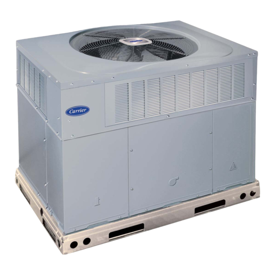
1
Fig. 1 - - Unit 50VT- -A
. . . . . . . . . . . . . . . . . . . . . . . . . . . . . . . .
. . . . . . . . . . . . . . . . . . . . . . . . . . . . . . . . . . . .
. . . . . . . . . . . . . . . . . . . . . . . . . . . . . . . . .
. . . . . . . . . . . . . . . . . . . . . . . . . . .
. . . . . . . . . . . . .
. . . . . . . . . . . . . . . . . . . . . . . . . . . . . . . .
. . . . . . . . . . . . . . . . . . . . . . . . . . . .
. . . . . . . . . . . . . . . . . . . . . . . . .
. . . . . . . . . . . . . . . . . . . . . . . . . . . . . .
. . . . . . . . . . . . . . . . . . . . . . . . . . . .
. . . . . . . . . . . . . . . . . . . . . . .
. . . . . . . . . . . . . . . . . . . . . . . . . . . . . . .
. . . . . . . . . . . . . . . . . . . . . . . . . . . . . . .
. . . . . . . . . . . . . . . . . . . . . . . . . . . . . .
. . . . . . . . . . . . . . . . . . . . . . . . . . . . . .
A09033
25
25
26
. . . .
26
26
26
26
26
26
26
26
29- -47
29
29
29- -35
29- -30
33- -35
36- -45
46
47
Advertisement
Table of Contents
Troubleshooting

Subscribe to Our Youtube Channel
Related Manuals for Carrier Performance 50VT-A24


Summary of Contents for Carrier Performance 50VT-A24
-
Page 1: Table Of Contents
50VT ---A Performancet 14 SEER Single ---Packaged Heat Pump System with Puron® (R ---410A) Refrigerant Single and Three Phase 2---5 Nominal Tons (Sizes 24---60) Installation Instructions NOTE: Read the entire instruction manual before starting the installation. NOTE: Installer: Make sure the Owner’s Manual and Service Instructions are left with the unit after installation. -
Page 2: Introduction
Follow all safety codes. Wear safety glasses, protective clothing, If the unit is to be mounted on a curb in a downflow application, and work gloves. Use quenching cloth for brazing operations. review Step 5 to determine which method is to be used to remove Have a fire extinguisher available. - Page 3 A09410 Fig. 2 - - 50VT- -A24- -30 Unit Dimensions...
- Page 4 A09411 Fig. 3 - - 50VT- -A36- -60 Unit Dimensions...
- Page 5 Dashed lines show cross support location for large basepan units. HVAC unit HVAC unit basepan base rails Sealing Gasket Roofcurb Anchor screw Wood nailer* Flashing field supplied Roofcurb* Insulation (field supplied) Roofing material field supplied Cant strip field supplied A09413 SMALL/COMMON CURB *Provided with roofcurb A09090...
-
Page 6: Rig And Place Unit
CAUTION - NOTICE TO RIGGERS PRUDENCE - AVIS AUX MANIPULATEUR ACCESS PANELS MUST BE IN PLACE WHEN RIGGING. PANNEAUX D'ACCES DOIT ÊTRE EN PLACE POUR MANIPULATION. Use top skid as spreader bar. / Utiliser la palette du haut comme barre de répartition DUCTS MINIMUM HEIGHT: 36"... -
Page 7: Select And Install Ductwork
Step 5 — Select and Install Ductwork CONFIGURING UNITS FOR DOWNFLOW (VERTICAL) DISCHARGE The design and installation of the duct system must be in accordance with the standards of the NFPA for installation of WARNING non- -residence type air conditioning and ventilating systems, NFPA 90A or residence- -type, NFPA 90B and/or local codes and ELECTRICAL SHOCK HAZARD ordinances. -
Page 8: Provide For Condensate Disposal
3. Use flexible transition between rigid ductwork and unit to prevent transmission of vibration. The transition may be OPTIONAL OPTIONAL screwed or bolted to duct flanges. Use suitable gaskets to RETURN SUPPLY ensure weather- -tight and airtight seal. OPENING OPENING 4. -
Page 9: Special Procedures For 208- -V Operation
between the thermostat and the unit. If the thermostat is located more than 100 ft (30.5 m) from the unit (as measured along the HIGH VOLTAGE control voltage wires), use no. 16 AWG color- -coded, insulated POWER LEADS POWER (SEE UNIT WIRING (35°... - Page 10 Table 1 – Physical Data - - Unit 50VT- -A 50VT-A24 50VT-A30 50VT-A36 50VT-A42 50VT-A48 50VT-A60 Unit Size Shipping Weight (lb) (kg) Compressor Quantity Type Scroll Refrigerant R-410A Refrigerant Quantity (lb) 11.1 10.3 11.3 12.5 15.2 Quantity (kg) Refrigerant Metering Device Indoor TXV, Outdoor Dual Accuraters Orifice OD (in) 0.032 (2)
- Page 11 A10197 Fig. 12 - - Connection Wiring Schematics 208/230- -1- -60...
- Page 12 A10197 Fig. 12 Cont. - - Ladder Wiring Schematics 208/230- -1- -60...
- Page 13 A10194 Fig. 13 - - Connection Wiring Schematics - - 208/230- -3- -60...
- Page 14 A10194 Fig. 13 Cont. - - Ladder Wiring Schematics - - 208/230- -3- -60...
- Page 15 A10195 Fig. 14 - - Connection Wiring Diagram 460- -3- -60...
- Page 16 A10195 Fig. 14 Cont. - - Ladder Wiring Diagram 460- -3- -60...
-
Page 17: Pre- -Start- -Up
PRE- - START- - UP high- -side Schrader fitting located on the compressor discharge line. Be sure that caps on the ports are tight. WARNING START- - UP Checking Cooling and Heating Control Operation FIRE, EXPLOSION, ELECTRICAL SHOCK AND Start and check the unit for proper control operation as follows: ENVIRONMENTAL HAZARD (1.) Place room thermostat SYSTEM switch or MODE Failure to follow this warning could result in personal injury,... -
Page 18: Checking & Adjusting Refrigerant Charge
turning backwards, the difference between compressor suction and WARNING discharge pressures may be near zero. Checking and Adjusting Refrigerant Charge ELECTRICAL SHOCK HAZARD The refrigerant system is fully charged with Puron (R- -410A) Failure to follow this warning could result in personal refrigerant and is tested and factory sealed. -
Page 19: Continuous Fan Operation
4. Remove the vinyl cap off of the desired speed tap wire CAUTION (Refer to Table 3 for color coding) for the normal cooling fan speed and place desired speed tap wire on “HIGH” on the interface board. UNIT OPERATION HAZARD 5. -
Page 20: Defrost Control
HIGH R13 C8 AB A15 D5 D3 R3 R5 R6 R W2 Y W3 W3 W2 W2 C SSTZ-8 A09059 Fig. 16 - - Interface Fan Board (IFB) INDOOR COIL OUTDOOR COIL TXV in Bypass Position HP S Metering Position LEGEND HPS –... -
Page 21: Maintenance
NOTE: Unit will remain in defrost until defrost thermostat each cooling season and twice during the heating season, or whenever the filter becomes clogged with dust and lint. reopens at approximately 65_F (18_C) coil temperature at liquid line or remainder of defrost cycle time. Indoor Blower and Motor MAINTENANCE NOTE: All motors are pre- -lubricated. - Page 22 Table 4 – Dry Coil Air Delivery CFM* - - Horizontal and Downflow Discharge - - Unit 50VT- -A24- -60 Wire Color External Static Pressure (in W.C) Unit Motor Speed Blue Med-Low Pink 50VT-A24 Medium Med-High Orange 1009 High Black 1241 1167 1111...
-
Page 23: Outdoor Coil, Indoor Coil, & Condensate Drain Pan
Step 2 — Outdoor Coil, Indoor Coil, and Rinse coils with clear water, using a garden hose. Be careful not to splash water on motors, insulation, wiring, or air filter(s). For best Condensate Drain Pan results, spray condenser coil fins from inside to outside the unit. On Inspect the condenser coil, evaporator coil, and condensate drain units with an outer and inner condenser coil, be sure to clean pan at least once each year. -
Page 24: Outdoor Fan
Speedup Quiet Defrost interval Pins Shift DIP switches A08020 Fig. 19 - - Defrost Control Step 3 — Outdoor Fan cycle to ensure proper operation. If discrepancies are observed in operating cycle, or if a suspected malfunction has occurred, check Keep the condenser fan free from all obstructions to ensure each electrical... -
Page 25: Pressure Switches
NOTE: Because these switches are attached to refrigeration system under pressure, it is not advisable to remove this device for troubleshooting unless you are reasonably certain that a problem exists. If switch must be removed, remove and recover all system charge so that pressure gauges read 0 psi. -
Page 26: Compressor Oil
Compressor Oil Check Defrost Thermostat The Copeland scroll compressor uses 3MAF POE oil. If additional The defrost thermostat is usually located on the lowest liquid oil is needed, use Uniqema RL32- -3MAF. If this oil is not leaving circuit of the left condenser coil (see Fig. 22). The available, use Copeland Ultra 32 CC or Mobil Arctic EAL22 CC. - Page 27 PURONR (R- -410A) QUICK REFERENCE GUIDE Puron refrigerant operates at 50- -70 percent higher pressures than R- -22. Be sure that servicing equipment and replacement components are designed to operate with Puron Puron refrigerant cylinders are rose colored. Recovery cylinder service pressure rating must be 400 psig, DOT 4BA400 or DOT BW400. Puron systems should be charged with liquid refrigerant.
- Page 28 Table 9 – Troubleshooting Chart SYMPTOM CAUSE REMEDY Power failure Call power company Fuse blown or circuit breaker tripped Replace fuse or reset circuit breaker Defective contactor, transformer, or high--pressure, Replace component loss--of--charge or low--pressure switch Compressor and condenser fan will not start. Insufficient line voltage Determine cause and correct Incorrect or faulty wiring...
-
Page 29: Vertical Economizer
VERTICAL ECONOMIZER ACCESSORIES (FACTORY INSTALLED OPTION) The economizer has several field- -installed accessories available to optimize performance. Refer to Table 12 for authorized parts. GENERAL Economizers are recommended for only commercial packaged Table 12 – Accessory List products that have X13 motors. The Economizer system utilizes DESCRIPTION PART NUMBER the latest technology available for integrating the use of free... - Page 30 6. Replace horizontal return duct cover panel. Screw in place ensuring all seams are air and watertight. 7. Install the 2 angle filter brackets to the right and left hood side panels respectively with the #10 screws provided. See Fig. 26. 8.
- Page 31 Hood Divider (Removed) Hood Divider Horizontal Return Duct Cover Panel A09691 Fig. 25 - - Horizontal Return Duct Cover Panel Removal Right Hood Left Hood Side Panel Side Panel Filter Angle Bracket Filter Angle Bracket A09692 Fig. 26 - - Filter Angle Bracket Installation...
- Page 32 Hood Top Panel Right Hood Side Panel Hood Divider Left Hood Side Panel A09693 Fig. 27 - - Economizer Hood Assembly Filter Clips Aluminum Filter A09694 Fig. 28 - - Economizer Hood Installation A09695 Fig. 29 - - Filter Installation (See Through View)
-
Page 33: Large Chassis
Large Chassis 7. Install the 2 angle filter brackets to the right and left hood side panels respectively with the #10 screws provided. See To install the Vertical Economizer on the large chassis perform the Fig. 33. following procedure: 8. Assemble hood according to Fig. 34 screwing together 1. - Page 34 A09698 Fig. 32 - - OAT Bracket Installation Left Hood Side Panel Filter Angle Bracket Right Hood Side Panel Filter Angle Bracket Left Hood Side Right Hood Side A09699 Fig. 33 - - Filter Angle Bracket Installation...
- Page 35 Right Hood Side Panel Hood Top Panel Left Hood Side Panel Hood Divider A09700 Fig. 34 - - Hood Assembly NOTE: The economizer control settings and the filters are accessible through the filter access door. Table 14 – Filter Part Number DESCRIPTION PART NUMBER 14 x 24 x 1...
-
Page 36: Configuration
CONFIGURATION Economizer Standard Sensors OUTDOOR AIR TEMPERATURE (OAT) SENSOR— The outdoor air temperature sensor (HH57AC080) is a 10 to 20mA device used to measure the outdoor- -air temperature. The outdoor- -air temperature is used to determine when the Economizer can be used for free cooling. - Page 37 TEMPERATURE COMPRESSOR LOCKOUT SWITCH—The Economizer is equipped with a low ambient temperature lockout switch located in the outdoor airstream which is used to lock out the compressors below a 42_F (5.6_C) ambient (8.9°C) temperature. Economizer Control Modes—Determine the Economizer control mode before set up of the control.
- Page 38 (29) (32) (25) (38) (41) (43) CONTROL CONTROL POINT CURVE APPROX ˚F (˚C) AT 50% RH (27) 73 (23) 70 (21) 24 Vac 67 (19) 63 (17) (24) Open (21) (18) (16) (13) (10) Free Cool A09712 Fig. 44 - - Economizer Controller DIFFERENTIAL ENTHALPY CONTROL —...
- Page 39 When demand ventilation control is not being used, the minimum 2. Disconnect the supply air sensor from terminals T and T1. position potentiometer should be used to set the occupied ventilation 3. Ensure that the factory- -installed jumper is in place across position.
- Page 40 A10059 Fig. 45 - - Economizer Wiring Diagram...
- Page 41 CONNECTION WIRING DIAGRAM DANGER: ELECTRICAL SHOCK HAZARD DISCONNECT POWER BEFORE SERVICING SCHEMATIC NOTES: 1. IF ANY OF THE ORIGINAL WIRES FURNISHED ARE REPLACED, IF USED 208/230-3-60 THEY MUST BE REPLACED WITH THE SAME WIRE OR ITS EQUIVALENT. 2. SEE PRICE PAGES FOR THERMOSTATS. 3.
- Page 42 A10200 Fig. 45 Cont. - - Ladder Wiring Diagram 230- -3...
- Page 43 A10199 Fig. 47 - - Connection Wiring Diagram 460- -3...
- Page 44 A10199 Fig. 46 Cont. - - Ladder Wiring Diagram 460- -3...
- Page 45 DAMPER MOVEMENT — Damper movement from full open to The DCV set point may be left at 2 volts since the CO sensor voltage will be ignored by the Economizer controller until it rises full closed (or vice versa) takes 2 1/2 minutes. above the 3.6 volt setting of the minimum position potentiometer.
-
Page 46: Operation
Table 16 – CO Sensor Standard Settings VENTILATION OPTIONAL RELAY RATE CONTROL RELAY ANALOG SETTING EQUIPMENT OUTPUT HYSTERESIS (CFM/ OUTPUT RANGE SETPOINT (PPM) PERSON) (PPM) (PPM) 0--- 10V Proportional 0--- 2000 1000 4--- 20mA Interface w/Standard Building 2--- 10V Proportional 0--- 2000 1000 Control System... -
Page 47: Troubleshooting
TROUBLESHOOTING 5. Turn the DCV set point potentiometer CW until the DCV LED turns off. The DCV LED should turn off when the See Table 17 for Economizer logic. An Economizer simulator potentiometer is approximately 9- -v. The actuator should program is available to help with Economizer training and drive fully closed. - Page 48 A10212 Fig. 48 - - 50VT- -A 30 3 Phase with Economizer...
- Page 49 A10213 Fig. 49 - - 50VT- -A 36- -60 3 Phase with Economizer...
- Page 50 { Measured at liquid line leaving condenser. Catalog No: 50VT ---07SI Copyright 2010 Carrier Corp. S 7310 W. Morris St. S Indianapolis, IN 46231 Edition Date: 04/10 Manufacturer reserves the right to change, at any time, specifications and designs without notice and without obligations.
Need help?
Do you have a question about the Performance 50VT-A24 and is the answer not in the manual?
Questions and answers