Carrier 19DK Operating And Maintenance Instructions Manual
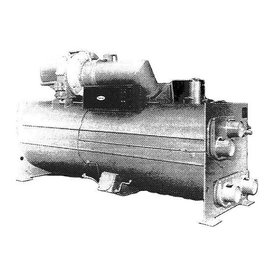
Hermetic centrifugal liquid chillers
Hide thumbs
Also See for 19DK:
- Product data (27 pages) ,
- Installation instructions manual (11 pages) ,
- Product data (24 pages)

Related Manuals for Carrier 19DK


Summary of Contents for Carrier 19DK
- Page 2 Contents List of Tables List of Figures Introduction Abbreviations Definitions Controls General Processor Board Input/Output Board Set Point/Display Board Safety Controls Reset Pushbutton Deadband Proportional Band...
- Page 3 Contents Ramp Loading Capacity Overrides Excessive Purge Pump Run Time Oil Heater and Thermostat Remote Start/Stop Controls Spare Safety Inputs Start-Up Sequence Shutdown Sequence Control Configuration Controls Test Before Initial Start-Up Job Data Required Equipment Required Check Machine Tightness...
- Page 4 Contents Inspect Piping Charge Refrigerant Inspect Wiring Check Starter Oil Charge Check Oil Heater Check Machine Safety Control Settings Configure DIP Switches Check Safety Control Operation Initial Start-Up Preparation Start-Up Calibrate Motor Current Demand Check Machine Operating Condition Trim Refrigerant Charge...
- Page 5 Contents Instruct the Customer Operator Compressor-Motor Assembly Unishell Purge System Lubrication System Control System Auxiliary Equipment Describe Machine Cycles Review Maintenance Safety Devices and Procedures Check Operator Knowledge Review Operating and Maintenance Instructions Operating Instructions Operator Duties Prepare Machine for Start-Up...
- Page 6 Contents To Start Machine Check Running System To Stop Machine After Limited Shutdown Extended Shutdown After Extended Shutdown Manual Operation Refrigeration Log Weekly Maintenance Check Lubrication System Check Purge Operation Scheduled Maintenance Inspect Control Center Check Safety and Operating Controls...
- Page 7 Contents Change Oil and Oil Filter Change Volute Drain Strainer and Refrigerant Filter Compressor Bearing Maintenance Inspect Purge Inspect Refrigerant Flow Chamber Inspect Unishell Tubes Inspect Starting Equipment Ordering Replacement Parts General Maintenance Refrigerant Properties Charging Refrigerant Removing Refrigerant Trimming Refrigerant Charge Refrigerant Loss...
- Page 8 Contents Air and Water Leaks Pressurizing a Machine When Liquid Refrigerant is Present Pressurizing a Machine When Liquid Refrigerant is Not Present Guide Vane Linkage Sensor Test Procedure General Data Machine Informative Plate System Components Refrigeration Cycle Motor Cooling Cycle Lubrication Cycle Summary Details...
- Page 9 Contents Compressor Fits and Clearances Control Troubleshooting Test Points Processor Board Replacement Input/Output Board Replacement Set Point/Display Board Replacement...
- Page 10 Contents List of Tables Table 1 — Safety Limits and Control Settings Table 2 — Capacity Override Set Points Table 3 — Configuration (DIP) Switch Settings Table 4 — Controls Test Table 5 — Machine Charge Table 6 — Oil Charge Table 7a —...
- Page 11 Figure 2 — Control Center Figure 3 — Control Wiring Schematic Figure 4 — Control Sequence Figure 5 — 19DK Leak Test Sequence and Procedures Figure 6 — Purge Valve and Switch Settings Figure 7 — Purge Component Location Figure 8 — Flow Chamber Poppet Valve Detail Figure 9 —...
Need help?
Do you have a question about the 19DK and is the answer not in the manual?
Questions and answers