Table of Contents
Advertisement
Quick Links
ALTENERGY POWER SYSTEM Inc.
aunz.APsystems.com
APsystems Australia
Suite 502, 8 Help Street, Chatswood NSW 2067, Australia
Tel: 02 8034 6587
EMAIL: info.aunz@APsystems.com
© All Rights Reserved
APsystems Microinverter
Installation manual
APsystems DS3D-AU Microinverter
(For Australia / New Zealand)
Please scan this QR code to
have access to our APPs and
Products information
Advertisement
Table of Contents

Related Manuals for APsystems DS3D-AU


Summary of Contents for APsystems DS3D-AU
- Page 1 APsystems Microinverter Installation manual APsystems DS3D-AU Microinverter (For Australia / New Zealand) ALTENERGY POWER SYSTEM Inc. aunz.APsystems.com Please scan this QR code to have access to our APPs and APsystems Australia Products information Suite 502, 8 Help Street, Chatswood NSW 2067, Australia Tel: 02 8034 6587 EMAIL: info.aunz@APsystems.com...
-
Page 2: Table Of Contents
4.3.1 Step 1 - Verify that grid voltage matches microinverter rating ........9 4.3.2 Step 2 – Y3 AC Bus Cable distribution ................9 4.3.3 Step 3 - Attach the APsystems Microinverters to the Racking ........9 4.3.4 Step 4 - Ground the system ....................10 4.3.5 Step 5 - Connect the APsystems microinverter to AC bus cable ......10... -
Page 3: Important Safety Instructions
Do NOT disconnect the PV module from the APsystems Microinverter without first disconnecting the AC power. Be aware that the body of the APsystems Microinverter is the heat sink and can reach a temperature of 80°C. To reduce risk of burns, do not touch the body of the Microinverter. -
Page 4: Radio Interference Statement
1.Important Safety Instructions 1.2 Radio Interference Statement EMC Compliance : The APsystems Microinverter can radiate radio frequency energy. If not installed and used in accordance with the instructions, it may cause harmful interference to radio communication. APsystems Microinverter complies with EMC regulations, which are designed to provide reasonable protection against harmful interference in a residential installation. -
Page 5: Symbols In Lieu Of Words
EMC and is authorized to energize, ground, and tag equipment, systems, and circuits in accordance with established safety procedures. The inverter and complete system may only be commissioned and operated by qualified personnel. APsystems Microinverter DS3D-AU Installation manual 4... -
Page 6: Apsystems Microinverter System Introduction
2.APsystems Microinverter System Introduction The APsystems Microinverter is used in utility-interactive grid-tied applications, comprised of three key elements: APsystems Microinverter APsystems Energy Communication Unit (ECU) APsystems Energy Monitor and Analysis (EMA) web-based monitoring and analysis system AC JUNCTION BOX... - Page 7 Simple to install APsystems Microinvertes are compatible with most of 60 and 72 cell PV modules or 120 and 144 half-cut cells PV modules. (In order to confirm compatibility of PV module with APsystems microinverter, feel free to check our online “E-decider”...
-
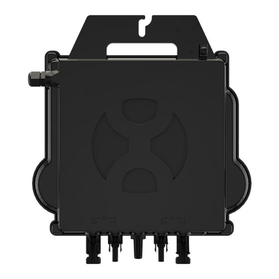
Page 8: Apsystems Microinverter Ds3D-Au Introduction
DS3D-L-AU, DS3D-AU and DS3D-H-AU. With unprecedented power outputs of 1600VA, 1800VA or 2000VA, the DS3D-AU series connects to 4 high power modules (2 by 2 in series). With 2 independent MPPTs, encrypted ZigBee signal, the DS3D-L-AU, DS3D-AU and DS3D-H-AU benefits from an entirely new architecture. -
Page 9: Apsystems Microinverter System Installation
4.APsystems Microinverter System Installation A PV system using APsystems Microinverters is simple to install. Each Microinverter easily mounts on the PV racking, directly beneath the PV module(s). Low voltage DC wires connect from the PV module directly to the Microinverter, eliminating the risk of high DC voltage. -
Page 10: Installation Procedures
4.3.3 Step 3 - Attach the APsystems Microinverters to the Racking a. Mark the location of the microinverter on the rack, with respect to the PV module junction box or any other obstructions. -
Page 11: Step 4 - Ground The System
Microinverter. Grounding lug Figure 3 4.3.5 Step 5 - Connect the APsystems microinverter to AC bus cable Insert the microinverter AC connector into the trunk cable connector. Make sure to hear the “click” as a proof of robust connection. Click Figure 4 Best Practice: Use the Bus Cable Unlock Tool of AC Bus to disconnect the connectors. -
Page 12: Step 6 - Install A Bus Cable End Cap At The End Of Ac Bus Cable
4.3.6 Step 6 - Install a Bus Cable End Cap at the end of AC bus cable C. Rotate the nut with 3.3N· m until the B. Insert the cable end A. Strip cable jacket. latching mechanism meets the base. into the seal. Figure 8 APsystems Microinverter DS3D-AU Installation manual 11... -
Page 13: Step 7 - Connect Apsystems Microinverters To The Pv Modules
4.APsystems Microinverter System Installation 4.3.7 Step 7 - Connect APsystems Microinverters to the PV Modules AC Output PV Ports PV Ports antenna Figure 9 Each channel connects 2 PV modules in series (For PV modules with Voc<60V). The input channel will not work if connects to a single module(Voc<60V). -
Page 14: Step 8 - Connect Apsystems Microinverters To Grid
Make sure to not split positive and negative DC cables into two different input channels: microinverter will be damaged and warranty will not apply. 4.3.8 Step 8 - Connect APsystems Microinverters to Grid ①.Please install bi-polar circuit breakers with proper rated current or according to the local regulation, which are mandatory to connect to grid. -
Page 15: Step 9 - Ac Extension Cable
Bus Cable End Cap When AC extension cable is needed, users could connect the AC bus cable and AC extension cable in a junction box or use a pair of male/female AC connectors that APsystems provides as optional accessory. 4.3.10 Step 10 - Complete the APsystems installation map a. - Page 16 The inverter power output will vary in response to the AC grid voltage.This is switched on by default. (Details of how to enable this mode are contained in the “APsystems ECU-R Install & User Manual” or “APsystems ECU-C Install Manual & User Manual”, which can be accessed at our website at https://aunz.apsystems.com/resources/library/.)
-
Page 17: Apsystems Microinverter System Operating Instructions
Alternatively, LED sequences could be an indicator of microinverters status (see section 6.1) Once the ECU has been commissioned properly, the APsystems Microinverters will start to send performance data to the ECU. The time required for all of the Microinverters in the system to report to the ECU will vary depending on the number of Microinverters in the system. -
Page 18: Troubleshooting
APsystems Technical Support. 6.2 ECU_APP APsystems ECU_APP (available in the EMA Manager APP) is the recommended tool to do on-site troubleshooting. When connecting the ECU_APP to the ECU hotspot (please check ECU User Manual for more detailed information), installer can check every microinverter status (production, communication) but also ZigBee signal strength, grid profile and other insightful data helping the troubleshooting. -
Page 19: Apsystems Technical Support
6.Troubleshooting 6.5 APsystems Technical Support APsystems local Technical Support team is available to support professional installers to get familiar with our products and to troubleshoot installations when needed. Do not attempt to repair APsystems Microinverters. Please contact your local APsystems Technical Support. -
Page 20: Replace A Microinverter
7.Replace a microinverter Follow the procedure to replace a failed APsystems Microinverter A. Disconnect the APsystems Microinverter from the PV Module, in the order shown below: 1. Disconnect the AC by turning off the branch circuit breaker. 2. Disconnect the inverter AC connector from the AC Bus. -
Page 21: Technical Data
8.Technical Data ①. Be sure to verify that the voltage and current specifications of your PV module are compatible with the range allowed on APsystems Microinverter. Please check the microinverter datasheet. ②. DC operating voltage range of the PV module must be within allowable input voltage range of the APsystems Microinverter. -
Page 22: Ds3D-Au Microinverter Datasheet
284mm X 234mm X 50.2mm Weight 4.3kg AC Bus Cable 4mm²(28A) DC Connector Type Stäubli MC4 PV-ADBP4-S2&ADSP4-S2 Cooling Natural Convection - No Fans Ingress Protection Rating IP67 Inverter Topology Isolated Active Anti-islanding Method Frequency shift APsystems Microinverter DS3D-AU Installation manual 21... - Page 23 (4) Recommend no more than 80 inverters register to one ECU for stable communication. (5) To be eligible for the warranty, APsystems microinverters need to be monitored via the EMA portal. Please refer to our warranty T&Cs available on aunz.APsystems.com.
-
Page 24: Ds3D-Au - Wiring Diagram
9. DS3D-AU - Wiring Diagram 9.1 Sample Wiring Diagram - Single Phase BROWN - L BLUE - N YELLOW GREEN - PE AC JUNCTION BOX DS3D BUS CABLE END CAP INSTALL AT THE END OF AC BUS CABLE ENERGY COMMUNICATION UNIT... -
Page 25: Apsystems Microinverter Installation Map
10. APsystems Microinverter Installation Map The APsystems Installation Map is a diagram of the physical location of each microinverter in your PV installation. Each APsystems microinverter has two serial number labels. Peel the one label and affix it to the respective location on the APsystems installation map.
Need help?
Do you have a question about the DS3D-AU and is the answer not in the manual?
Questions and answers