
Related Manuals for SincoSald NOVATIG 325 DC


Summary of Contents for SincoSald NOVATIG 325 DC
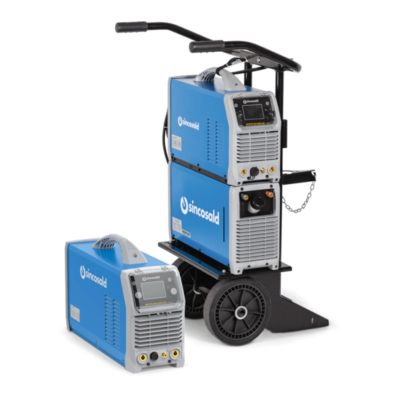
- Page 1 MODEL NOVATIG 325 DC NOVATIG 505 AC/DC G.R.W. INSTRUCTION MANUAL for installation, use and maintenance of welding machines. Original instructions in Italian. Please keep for future use. 1.995.202 EN - Rev. 1.1...
-
Page 2: Table Of Contents
NOVATIG 325 DC - NOVATIG 505 AC/DC G.R.W. Contents 1. PREFACE 1.1. PURPOSE OF THE INSTRUCTION MANUAL FOR USE AND MAINTENANCE 1.2. RECIPIENTS 1.3. STORAGE OF THE INSTRUCTION MANUAL 1.4. UPDATING THE INSTRUCTION MANUAL 1.5. HOW TO READ THE INSTRUCTION MANUAL 1.6. - Page 3 NOVATIG 325 DC - NOVATIG 505 AC/DC G.R.W. 6. MACHINE USE 6.1. MACHINE LAYOUT DESCRIPTION 6.1.1. Layout for the front panel 6.1.2. Layout for the rear panel 6.1.3. Preparing for welding 6.2. FRONTAL PANEL NOVATIG 325 DC 6.2.1. Interface user 6.3.
-
Page 4: Preface
NOVATIG 325 DC - NOVATIG 505 AC/DC G.R.W. 1. PREFACE THE OFFICIAL LANGUAGE CHOSEN BY THE MANU- FACTURER IS ITALIAN. The manufacturer cannot be held liable for translations in other languages that do 1.1. PURPOSE OF THE INSTRUCTION not conform to the original meaning (ORIGINAL IN- MANUAL FOR USE AND MAINTENANCE STRUCTIONS). -
Page 5: Storage Of The Instruction Manual
NOVATIG 325 DC - NOVATIG 505 AC/DC G.R.W. 1.5. HOW TO READ • capable of comprehending and interpreting the operator manual and the safety instructions; THE INSTRUCTION MANUAL • familiar with the emergency procedures and how The Manual is split into chapters, each one dedicated to implement them;... -
Page 6: General Information
NOVATIG 325 DC - NOVATIG 505 AC/DC G.R.W. 2. GENERAL INFORMATION NOVATIG 325 DC Plate 2.1. MANUFACTURER IDENTIFICATION DATA MANUFACTURER: SINCOSALD S.r.l HEADQUARTERS - OFFICES via della Fisica, 26/28 20864 Agrate Brianza (MB) Italy Tel: +39 039 641171 Fax: +39 039 6057122... - Page 7 NOVATIG 325 DC - NOVATIG 505 AC/DC G.R.W. NOVATIG 325 DC plate explanation NOVATIG 505 AC/DC Plate Pos. 1 Name and address of the manufacturer and trademark Pos. 2 Identification of the welding machine model Pos. 3 Welding machine serial number Pos.
-
Page 8: Declarations Of Conformity
NOVATIG 325 DC - NOVATIG 505 AC/DC G.R.W. NOVATIG 325 DC plate explanation G.R.W. plate Pos. 1 Name and address of the manufacturer and trademark Pos. 2 Identification of the welding machine model Pos. 3 Welding machine serial number Pos. 4... -
Page 9: Information On Technical Assistance
NOVATIG 325 DC - NOVATIG 505 AC/DC G.R.W. 2.5. INFORMATION 3. SAFETY ON TECHNICAL ASSISTANCE 3.1. GENERAL SAFETY WARNINGS The machines are covered by a warranty, as provided for in the general conditions of sale. WARNING: your safety depends on you!!! If during the warranty period you experience a mal- - Follow all safety rules carefully. - Page 10 NOVATIG 325 DC - NOVATIG 505 AC/DC G.R.W. anisms installed on the machine; A) Electric shock • Operations at reduced safety levels must be car- ELECTRIC SHOCK CAN BE FATAL!!! ried out in strict accordance with the instructions - All electric shocks are potentially fatal.
- Page 11 NOVATIG 325 DC - NOVATIG 505 AC/DC G.R.W. - Prepare the welding area so as to reduce reflection 2) Pressure regulators: and transmission of ultraviolet radiation: paint - Keep pressure regulators in good condition. Dam- walls and exposed surfaces black to reduce reflec-...
- Page 12 NOVATIG 325 DC - NOVATIG 505 AC/DC G.R.W. the protective glass if it is broken, pitted or spotted. the operation is completed and before restarting the Avoid oily or greasy clothes; a spark could ignite machine. them. Incandescent metal parts, such as work pieces, I) Noise should always be handled with gloves.
- Page 13 NOVATIG 325 DC - NOVATIG 505 AC/DC G.R.W. g) The health of people in the vicinity, for example C) Cables people who use pacemakers and earphones for Cables must be kept as short as possible and must be hearing. placed close to each other and passed on the floor or h) The daily duration of welding operations or other as low as possible.
-
Page 14: Intended Use
NOVATIG 325 DC - NOVATIG 505 AC/DC G.R.W. The results of these checks must be reported on a • In explosive, corrosive atmospheres or with a high specific sheet. concentration of dust or oily substances suspend- ed in the air;... -
Page 15: Signs
NOVATIG 325 DC - NOVATIG 505 AC/DC G.R.W. 3.6. SIGNS The safety signs must always be clearly visible and it is absolutely forbidden to remove or hide them. Generally there are signals or signs on the machine or in the work environment that indicate dangerous... -
Page 16: Residual Risks
NOVATIG 325 DC - NOVATIG 505 AC/DC G.R.W. 4. INSTALLATION 4.1. SHIPPING The shipment, also depending on the destination, can be carried out by different means. The packed machine must be properly anchored to the means of transport in order to avoid uncontrolled movements. -
Page 17: Handling And Lifting
NOVATIG 325 DC - NOVATIG 505 AC/DC G.R.W. 4.4. HANDLING AND LIFTING IMPORTANT: The Manufacturer cannot be held liable for damage caused to persons or property ATTENTION: handling and lifting must be carried due to utilising lifting systems other than those out by trained and qualified operators, using described above. -
Page 18: Storage
NOVATIG 325 DC - NOVATIG 505 AC/DC G.R.W. The machine has a sturdy handle integrated in the frame for handling. N.B. These lifting and handling devices com- ply with the provisions prescribed by European standards. Do not use other devices such as lifting and handling equipment. -
Page 19: Assembly/Positioning
NOVATIG 325 DC - NOVATIG 505 AC/DC G.R.W. 4.9. CONNECTIONS in Laws and/or Technical Standards currently in force for safety in workplaces and electrical installations. Electrical connections Appropriate safety devices must be provided for its The machine's internal connections are carried out operation in line with those required in the area of by qualified personnel sent by the manufacturer. -
Page 20: Preliminary Checks
NOVATIG 325 DC - NOVATIG 505 AC/DC G.R.W. 5. OVERVIEW ATTENTION: the yellow-green wire of the welding machine power cable must always be connected to the protection conductor (system earth). The 5.1. OPERATING PRINCIPLE yellow-green wire should NEVER be combined with another phase wire for a voltage withdrawal. -
Page 21: Environmental Conditions
NOVATIG 325 DC - NOVATIG 505 AC/DC G.R.W. 5.5. VIBRATIONS • Dual digital display for accurate pre-setting and feedback of welding parameters & output. Under operating conditions that comply with the in- • Remote control potentiometer of the torch and dications for proper use, the vibrations are not such the amperage on it (optional). -
Page 22: Technical Specifications
NOVATIG 325 DC - NOVATIG 505 AC/DC G.R.W. 5.7. TECHNICAL SPECIFICATIONS The following table shows the main technical specifications relating to the machine: Parameters NOVATIG 325 DC NOVATIG 505 AC/DC Three-phase feed 400 V- 50/60 Hz 400 V- 50/60 Hz MAX current 37.3A... -
Page 23: Machine Use
NOVATIG 325 DC - NOVATIG 505 AC/DC G.R.W. 6. MACHINE USE 6.1.2. Layout for the rear panel 6.1. MACHINE LAYOUT DESCRIPTION 6.1.1. Layout for the front panel USB - 3 RC - B FUSION USB - 3 RC - B FUSION 1. -
Page 24: Preparing For Welding
NOVATIG 325 DC - NOVATIG 505 AC/DC G.R.W. 6.1.3. Preparing for welding 1. Set the welding power source ON/OFF switch to “O” (unit de-energized). 1. Set the welding power source ON/OFF switch to 2. Plug the power cable plug into a mains socket “O”... - Page 25 NOVATIG 325 DC - NOVATIG 505 AC/DC G.R.W. USB - 3 RC - B FUSION 1.995.202 EN - Rev. 1.1...
- Page 26 NOVATIG 325 DC - NOVATIG 505 AC/DC G.R.W. USB - 3 RC - B G.R.W. FUSION G.R.W. 1.995.202 EN - Rev. 1.1...
-
Page 27: Frontal Panel Novatig 325 Dc
NOVATIG 325 DC - NOVATIG 505 AC/DC G.R.W. 6.2. Frontal panel NOVATIG 325 DC 6.2.1. Interface user L5 L4 L3 L6 D1 SPOT STICK PULS - ST. TIG DC TIG PULS TIG SYN L 20 L 21 L 22 L 23... - Page 28 NOVATIG 325 DC - NOVATIG 505 AC/DC G.R.W. CODE DESCRIPTION Illuminates to show a value in the following unit of measurement: AMPERES Illuminates to show the last voltage and current values measured during welding. The value appears on the following displays: D1-D2 The LED switches off when a new welding procedure is started, or when any of the welding settings is modified.
- Page 29 NOVATIG 325 DC - NOVATIG 505 AC/DC G.R.W. CODE DESCRIPTION This LED illuminates to show that the following welding mode is selected: TIG DC CONTINUOUS This LED illuminates to show that the following welding mode is selected: PULSED DC TIG...
-
Page 30: Frontal Panel Novatig 505 Ac/Dc
NOVATIG 325 DC - NOVATIG 505 AC/DC G.R.W. 6.3. Frontal panel NOVATIG 505 AC/DC 6.3.1. Interface user L5 L4 L3 L6 D1 AC/DC % PULS - ST. SPOT FUSION F. AC STICK / AIR / PULS BALANCE D. ELETT. TIG SYN... - Page 31 NOVATIG 325 DC - NOVATIG 505 AC/DC G.R.W. CODE DESCRIPTION Illuminates to show the last voltage and current values measured during welding. The value appears on the following displays: D1-D2. The LED switches off when a new welding procedure is started, or when any of the welding settings is modified.
- Page 32 NOVATIG 325 DC - NOVATIG 505 AC/DC G.R.W. CODE DESCRIPTION Illumination shows that the following function has been activated: 2 stroke spot procedure (Q-SPOT). This LED illuminates to show that the following welding mode is selected: MMA This LED illuminates to show that the following welding mode is selected: DESEAMING MODE...
-
Page 33: Unit Power - Up
NOVATIG 325 DC - NOVATIG 505 AC/DC G.R.W. 6.4. UNIT POWER - UP Set the welding power source ON/OFF switch to “I” to switch on the unit. Fx.x The message appears on the following displays: D2 x.x = software version First power-up or power-ups following a RESET procedure. -
Page 34: Set-Up ( Initial Set-Up Of The Welding Power Source )
NOVATIG 325 DC - NOVATIG 505 AC/DC G.R.W. Exit without confirmation Press any button (except S3). • This action will automatically close the menu. Exit with confirmation Press the button. Wait for the memory clear procedure to terminate. • This action will automatically close the menu. - Page 35 NOVATIG 325 DC - NOVATIG 505 AC/DC G.R.W. Power-up with operation of the cooler set to "ON" or "AUT" mode A check is performed automatically of the presence of liquid in the cooling circuit and the cooler is switched on for 15 seconds. If the coolant circuit is full, the power source sets up in the most recent stable welding con- figuration.
-
Page 36: Welding Settings
NOVATIG 325 DC - NOVATIG 505 AC/DC G.R.W. 6.6. WELDING SETTINGS 4 STROKE WELDING WITH HIGH FREQUENCY ARC STRIKE (4T HF) 1. Bring the torch up to the work until the electrode 6.6.1. TORCH TRIGGER PROCEDURE tip is approximately 2 or 3 mm away. - Page 37 NOVATIG 325 DC - NOVATIG 505 AC/DC G.R.W. tomatically. • Gas delivery continues for the time set in the • The welding current reaches the preset value, post gas parameter. by way of a up slope time, if programmed. Keep pressed torch trigger procedure 3.
- Page 38 NOVATIG 325 DC - NOVATIG 505 AC/DC G.R.W. SELECTION OF THE WELDING MODE AND TORCH Legenda TRIGGER PROCEDURE 2 STROKE LIFT-ARC Specific torch trigger procedures are available in ac- 2T HF: 2 STROKE WITH HIGH FREQUENCY cordance with the selecting welding mode.
- Page 39 NOVATIG 325 DC - NOVATIG 505 AC/DC G.R.W. WELDING PARAMETERS interposed between the electrode tip as it is fusing For a better understanding of the parameter functions and the workpiece. This condition results in an inter- described in the table, refer to the following diagram.
- Page 40 NOVATIG 325 DC - NOVATIG 505 AC/DC G.R.W. the welding process when the geometry of the work- POST GAS TIME piece changes; alternatively, the welding current can Time of post gas delivery when the welding arc is ex- be reduced to decrease heating of the part if it be- tinguished.
- Page 41 NOVATIG 325 DC - NOVATIG 505 AC/DC G.R.W. MINIMUM PEDAL CURRENT FUSION Minimum output current value with foot pedal con- This parameter establishes the percentage of the troller external reference. positive current wave (pickling) that is subtracted The current is set as a percentage with respect to the and added to the negative current (fusion).
- Page 42 NOVATIG 325 DC - NOVATIG 505 AC/DC G.R.W. AC BALANCE LEGENDA This parameter establishes the positive wave vs. neg- Always available. ✓ ative wave time ratio. Available with the following setting: SPOT = The following figure shows two graphs with different...
- Page 43 NOVATIG 325 DC - NOVATIG 505 AC/DC G.R.W. MODE STICK TIG DC PULS TYG SIN PROCEDURE 4T -_- SPOT 4T -_- SPOT 4T -_- SPOT MENU PARAMETER 1° WELDING CURRENT ✓ ✓ ✓ ✓ ✓ ✓ ✓ ✓ ✓ ✓...
- Page 44 NOVATIG 325 DC - NOVATIG 505 AC/DC G.R.W. MODE TIG AC PULS PROCEDURE 4T -_- SPOT 4T -_- SPOT MENU PARAMETER 1° WELDING CURRENT 1° HOT-START 1° ARC FORCE 1° PRE-GAS TIME 1° STARTING CURRENT ✓ ✓...
- Page 45 NOVATIG 325 DC - NOVATIG 505 AC/DC G.R.W. PARAMETERS SETTING : (1ST LEVEL) Press this button to scroll the list of settings to edit. • The acronym relative to the setting to be edited appears on the following displays: D1 •...
- Page 46 NOVATIG 325 DC - NOVATIG 505 AC/DC G.R.W. ACRONYM PARAMETER DEFAULT MAX PE.t. PEAK TIME 50 % 99 % P.Fr. PULSED CURRENT FREQUENCY 0.1 Hz 100 Hz 2.5 kHz bA.t. BASE TIME 0.1 s 5.0 s 5.0 s Sl.d. DOWN SLOPE 0.0 s...
- Page 47 NOVATIG 325 DC - NOVATIG 505 AC/DC G.R.W. 1st level menu parameters in AC TIG mode ACRONYM PARAMETER DEFAULT MAX Pr.G. PRE-GAS TIME 0.0 s 0.1 s 10.0 s St.C. STARTING CURRENT 50 A 500 A 50 % 200 % Sl.u.
- Page 48 NOVATIG 325 DC - NOVATIG 505 AC/DC G.R.W. PARAMETERS SETTING: (2ND LEVEL) Hold down the button for 3 seconds to gain access to the 2nd level menu. • The acronym relative to the setting to be edited appears on the following displays: D1 •...
- Page 49 NOVATIG 325 DC - NOVATIG 505 AC/DC G.R.W. ACRONYM PARAMETER DEFAULT Value WAVE- FORM SP.t. SPOT TIG TIME 0.01 s 0.1 s 10.0 s HF ARC STRIKE ENABLE on r.P.C. MINIMUM PEDAL 90 % CURRENT PARAMETERS SETTING: SPECIAL FUNCTIONS Press this button to scroll the list of settings to edit.
- Page 50 NOVATIG 325 DC - NOVATIG 505 AC/DC G.R.W. JOBS MANAGEMENT - Personalised welding settings, or JOBs, can be saved in memory locations and subsequently uploaded. Up to 50 JOBS can be saved (j01-j50). - JOBs can be managed only when the unit is not in welding mode.
- Page 51 NOVATIG 325 DC - NOVATIG 505 AC/DC G.R.W. DELETING A JOB Hold down the button for 3 seconds • SA. Job The message appears on the following displays: D1-D2 Select the following setting with the encoder: Er. Job The message appears only if there are saved JOBS, on the following displays: D1-D2 Press the button to confirm.
-
Page 52: Remote Control Configuration
NOVATIG 325 DC - NOVATIG 505 AC/DC G.R.W. 6.7. REMOTE CONTROL 3. Pressing the encoder about 10 seconds, until the control panel display "rSt", then it sucuceed. CONFIGURATION 6.7.1. Wireless remote control Configuration 6.7.2. Wire foot pedal Configuration TIG series of welding machines can be configured to •... -
Page 53: Maintenance
NOVATIG 325 DC - NOVATIG 505 AC/DC G.R.W. 7. MAINTENANCE 7.4. ROUTINE MAINTENANCE General requirements 7.1. MACHINE ISOLATION The machine is designed to minimise routine main- tenance, thus it is up to the operator to assess its Before carrying out any type of Maintenance or Re- condition and suitability for use. -
Page 54: Welding Machine Repairs
NOVATIG 325 DC - NOVATIG 505 AC/DC G.R.W. ATTENTION: These operations, although simple, - If repairs are not carried out by the manufacturer, must be performed by a Qualified or Qualified repaired welding machines, in which some com- and Authorised Technician. -
Page 55: Diagnostics And Troubleshooting
NOVATIG 325 DC - NOVATIG 505 AC/DC G.R.W. 7.6. DIAGNOSTICS AND TROUBLESHOOTING For defects or malfunctions of the machine not described in this manual, please contact the manufacturer. List of error code MESSAGE MEANING EVENT CHECKS Overheating alarm All functions disabled. - Page 56 NOVATIG 325 DC - NOVATIG 505 AC/DC G.R.W. MESSAGE MEANING EVENT CHECKS Alarm, no-load voltage failure All functions disabled. - Check to ensure the welding Exceptions: torch is not resting on the - Cooling fan. workpiece connected to ground. - Check that when the power...
-
Page 57: Accessories And Spare Parts
NOVATIG 325 DC - NOVATIG 505 AC/DC G.R.W. 8. ACCESSORIES AND SPARE PARTS 9. ADDITIONAL INSTRUCTIONS 8.1. CUSTOMER SERVICE 9.1. WASTE DISPOSAL The Manufacturer is always at your disposal for any It is the responsibility of the user, in accordance with... - Page 58 NOVATIG 325 DC - NOVATIG 505 AC/DC G.R.W. There are 2 ways to discard DOMESTIC WEEE: Per la gestione dei "RAEE" la SINCOSALD si affida a) If you decide to buy a new equivalent equipment, a Consorzio Erion the user can deliver it to the distributor, who will have to collect it for free.
-
Page 59: Annexes
NOVATIG 325 DC - NOVATIG 505 AC/DC G.R.W. 10. ANNEXES 10.1. WIRING DIAGRAMS Wiring diagram G.R.W. 1.995.202 EN - Rev. 1.1... - Page 60 NOVATIG 325 DC - NOVATIG 505 AC/DC G.R.W. Wiring diagram NOVATIG 325 - 505 AC/DC 1.995.202 EN - Rev. 1.1...
- Page 61 NOVATIG 325 DC - NOVATIG 505 AC/DC G.R.W. Wiring diagram A 1.995.202 EN - Rev. 1.1...
- Page 62 NOVATIG 325 DC - NOVATIG 505 AC/DC G.R.W. Wiring diagram B 1.995.202 EN - Rev. 1.1...
- Page 63 NOVATIG 325 DC - NOVATIG 505 AC/DC G.R.W. Wiring diagram C 1.995.202 EN - Rev. 1.1...
- Page 64 NOVATIG 325 DC - NOVATIG 505 AC/DC G.R.W. Wiring diagram D 1.995.202 EN - Rev. 1.1...
-
Page 65: Spare Parts
NOVATIG 325 DC - NOVATIG 505 AC/DC G.R.W. 10.2. SPARE PARTS Spare parts NOVATIG 325 DC 1.995.202 EN - Rev. 1.1... - Page 66 NOVATIG 325 DC - NOVATIG 505 AC/DC G.R.W. Pos. Code Description Pos. Code Description Pos. Code Description ALIMENTAZIONE4G4 7.225.035 BLUE KNOB HOOD 7.221.033 COVER LEFT SIDE 7.225.047 CABLE TARGA FRONT THERMAL 7.223.015 7.225.042 LAM. SUPP. TUNNEL NOVATIG 325 DC PROTECTOR 75 ° C 7.221.012...
- Page 67 NOVATIG 325 DC - NOVATIG 505 AC/DC G.R.W. Spare parts NOVATIG 505 AC/DC 1.995.202 EN - Rev. 1.1...
- Page 68 NOVATIG 325 DC - NOVATIG 505 AC/DC G.R.W. Pos. Code Description Pos. Code Description Pos. Code Description PLUG FOR RS-232 7.225.035 BLUE KNOB HOOD 7.223.004 SNUBBER SHEET 7.225.045 WIRED TARGA FRONT BRACKET COPPER 7.223.015 7.221.007 7.225.046 GLAND PG21 NOVATIG 505 AC/DC MODULE INV./OUT...
- Page 69 NOVATIG 325 DC - NOVATIG 505 AC/DC G.R.W. Spare parts G.R.W. Pos. Code Description 5.725.035 RADIATOR 1.020.011 3.022.004 ELECTROPUMP 1.023.033 TANK 5.035.220 PRESSOSTATE 1.023.035 PLASTIC FRONTAL 1.995.202 EN - Rev. 1.1...
- Page 70 NOVATIG 325 DC - NOVATIG 505 AC/DC G.R.W. 1.995.202 EN - Rev. 1.1...
- Page 71 NOVATIG 325 DC - NOVATIG 505 AC/DC G.R.W. 1.995.202 EN - Rev. 1.1...
- Page 72 SINCOSALD S.r.l Headquarters - Offices via della Fisica, 26/28 20864 Agrate Brianza (MB) Italy Tel: +39 039 641171 Fax: +39 039 6057122 export@sincosald.it www.sincosald.it...
Need help?
Do you have a question about the NOVATIG 325 DC and is the answer not in the manual?
Questions and answers