Table of Contents
Advertisement
Quick Links
VECOAX MINIMOD 2 PLUS
INSTRUCTION MANUAL
V1.4 JULY 2022
The information in this document is subject to change without notice. Although PVI strives to improve and update our documentation as time passes,
ProVideoInstruments is not responsible for any misinformation or incompleteness. Any concerns may be brought forward to our support staff.
Advertisement
Table of Contents

Related Manuals for PVI VECOAX MINIMOD 2 PLUS


Summary of Contents for PVI VECOAX MINIMOD 2 PLUS
- Page 1 V1.4 JULY 2022 The information in this document is subject to change without notice. Although PVI strives to improve and update our documentation as time passes, ProVideoInstruments is not responsible for any misinformation or incompleteness. Any concerns may be brought forward to our support staff.
-
Page 2: Table Of Contents
Table of Contents Before Installation ..............................5 Technical Specifications ............................6 Modulation Specs ..............................7 • ATSC or QAM ............................7 • ISDB-T(b) ..............................7 • DVB-C ................................ 8 • Video Quality ............................8 • Audio Codec ............................. 8 Unit Overview ................................. 9 •... - Page 3 DVB-T Over-the-Air TV with HDMI Modulation ....................29 ISDB-T(b) Over-the-Air TV with HDMI Modulation ....................32 DVB-C Cable TV with HDMI Modulation ....................... 35 Web Configuration / Remote Control ........................38 • Assigning a Static IP............................ 39 • Network Connection Via Windows PC ....................39 •...
- Page 4 • The HDMI Video stretches or shrinks on TV ..................57 P a g e ProVideoInstruments – Minimod 2 Plus...
-
Page 5: Before Installation
Before Installation Unit out of the box is set to Clear QAM (Digital Cable) on Channel 77.1. Connect it to your TV's tuner and auto scan for digital TV to find the unit. No adjustments are needed to be done on the unit for a single channel unit. If installing multiple, Refer to Installing multiple units section of the manual. -
Page 6: Technical Specifications
Technical Specifications HDMI Input resolution: 1080p | 1080i| 720p| 576p| 576i| 480p| 480i @ 24|50|60fps Output Resolution: Same as input HDMI Audio Format: Dolby Digital Stereo LPCM RF frequency range: 5 - 999 MHz RF Channel Bandwidth: 6/7/8 MHz Model specific to the broadcast format Channel Range: 2-83 ATSC Mode | 2-158 QAM mode RF Output power: -8dBm | ~40dBmv RF Connector type: F-Type Dual... -
Page 7: Modulation Specs
Modulation Specs • ATSC or QAM Modulator Type ATSC-Air (8VSB) or QAM-Cable (J.83B) Frequency Range 50 MHz to 860 MHz Channel Bandwidth 6 MHz Technique ATSC 8VSB J.83B 64QAM, 128QAM, 256QAM ≥35 dB DVB-T Frequency Range 50 MHz to 860 MHz Channel Bandwidth 6 MHz (Colombia/Panama), 7 MHz (Australia), 8 MHz (Europe, New Zealand) -
Page 8: Dvb-C
• DVB-C Frequency Range 50 MHz to 860 MHz Channel Bandwidth 8 MHz Symbol Rate editable, 6.875 Mbps Technique 16QAM, 32QAM, 64QAM, 128QAM, 256QAM • Video Quality Video quality has been optimized by determining the size and the speed of transmitting MPEG packets to the TV. -
Page 9: Unit Overview
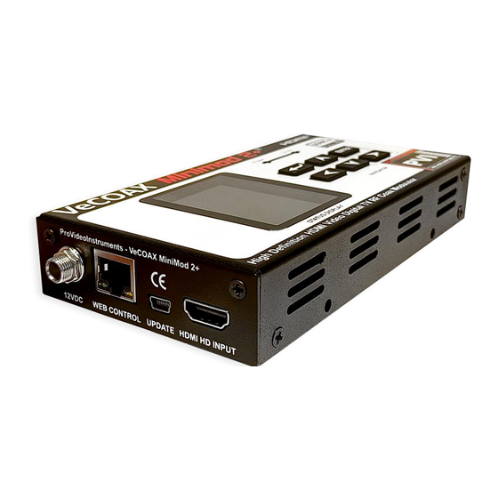
Unit Overview • Panel 2.4" color LCD Keypad • Return or Escape to the upper- level menu and confirm the current operation ◄►▲▼ Arrow keys to traverse between fields or increase/decrease selected field value Confirm the selection • LEDS Power solid Power Indication ON-AIR solid... -
Page 10: Tv Standards Supported
• TV Standards Supported Cable TV (USA) J.83B Over-the-Air TV (USA) ATSC (8VSB), ATSC 3.0(future) Cable TV (EU, SA) DVB-C (J.83A/C) Over-the-Air TV (CO) DVB-T Over-the-Air (SA) ISDB-T(b) 10 | P a g e ProVideoInstruments – Minimod 2 Plus... -
Page 11: Lcd Configuration Menu
LCD Configuration Menu • CHANNEL SETUP Television Standard – Current Television Standard is currently used. To change the standard, use the General setup menu to adjust. Depending on the standard used for Modulation, different options appear to change the available Channel by plan numbers, such as UK standards or EU standards. Channel by Plan –... -
Page 12: Channel Setup(Continued)
• CHANNEL SETUP(CONTINUED) Channel Sub Number - Specify the channel number displayed on the TV. This is the sub-virtual channel number. Only required to change if you wish to customize the channel plan layout XX.XX Example XX.10 Press OK to edit the subchannel number, ◄► to move the cursor and ▲▼ to change subchannel number, press RETURN to save and escape. -
Page 13: Modulation Options
• MODULATION OPTIONS Modulation Mode – Set the advance options for the modulation mode choice for the current TV standard, such as QAM mode, Symbol rate, GI, or Code Rate, for example. press ◄► to change modulation technique. Technique press OK to edit symbol rate in MHz, ◄► to move the cursor, and ▲▼ to change Symbol Rate symbol rate. -
Page 14: Advanced Settings
• ADVANCED SETTINGS Advance settings must only be modified if your application, such as Community channel cable insertion or applications, deems it necessary. Applications such as where the IDs need to be a specific ID to work correctly. Default values are designed to work correctly for most applications. Please only change these if you clearly understand Modulation and PSIP broadcast tables. -
Page 15: Advanced Settings(Continued)
• ADVANCED SETTINGS(CONTINUED) Changing MPEG Transport Stream (TS) parameters is not recommended unless you understand the MPEG PID structure well or your Service Provider requires you to configure a specific Packet Identifier (PID) describing the payload data for set-top box initialization. Refer to Wikipedia for more information about MPEG Transport Stream structure. -
Page 16: General Setup
• GENERAL SETUP UI Language – Select the Language for the menu. Then, press◄► to change the on-screen-display language. TV Standard – Select the TV standard you wish to use for your application. Press◄► to change modulator standard type. USA Cable J.83B, USA Air ATSC, ISDB-T, DVB-T, DVB-C, DTMB. IP Mode –... -
Page 17: Combining With Other Tv Coax Signals
Combining With Other TV Coax Signals To combine the existing TV broadcasting channels from a service provider, free Over-the-Air channels, or other modulators, it's necessary to select an output frequency and output channel for the unit to broadcast on that currently is not in use. ➢... -
Page 18: How To Assign A Channel
• HOW TO ASSIGN A CHANNEL Depending on the TV Standard of over-the-air broadcasting(ATSC) or Cable TV(QAM) used in your area, refer to the corresponding appendix for Channel Plan information or use the guides found further within the manual for your specific standard used when mixing with other coax cable signals. The following information provides a generic setup for broadcasting your HDMI signal over RF. -
Page 19: Generic Setup (Usa/Canada/Mexico)
• GENERIC SETUP (USA/CANADA/MEXICO) → The on-screen-display language can be changed by going to General Setup UI Language. 1. Power on the Modulator with a power adapter included in the package if you have not done so already. 2. Connect your coax cable to the RF out of the Modulator. If you wish to use the Minimod 2 Plus inline with your existing Coax cable without a splitter, you may use the RF Mix in and RF out ports. - Page 20 77. 11. The PVI TEST PATTERN is displayed on the TV as long as no HDMI is connected. 12. Connect the HDMI from your video players or input devices like DVD player, Satellite TV Set-Top Box, Video Stream, Security monitors...
-
Page 21: Installing Multiple Modulators
Unit 3: Channel 79.1 555mhz Unit 4: Channel 80.1 561mhz 2. Channel name default channel name is PVI HD1; the channel naming can be PVI HDn, where n indicates the modulator count or your custom name up to 7 characters, including a space. -
Page 22: Installing Multiple Modulators (Continued)
• INSTALLING MULTIPLE MODULATORS (CONTINUED) If the unit is used together with other brands of modulators, harmonic settings of RF output (power) level, and output frequency must be found. Make a note on each Modulator with RF output level and output frequency for quick reference for easy troubleshooting whenever needed. -
Page 23: Atsc Over-The-Air Tv With Hdmi Modulation
ATSC Over-the-Air TV with HDMI Modulation If the TV signal comes from an outdoor or indoor antenna, follow the steps below to combine the Modulator with an over-the-air TV signal. A crucial step is to verify the currently used channels within your area. This would require the Physical Frequency to be found, NOT the Virtual channel number displayed on the TV, such as 22.1 or 30.2. - Page 24 In some applications, the default settings may work as a plug-and-play device if your local area channels don't use the same Frequency. If you are unsure it will or If you plan to customize the settings, refer to the section below: →...
- Page 25 77. 10. The PVI TEST PATTERN is displayed on the TV as long as no HDMI is connected. 11. Connect the HDMI from your video players or input devices like DVD player, Satellite TV Set-Top Box, Video Stream, Security monitors...
-
Page 26: Exsisting Cable Tv With Hdmi Modulation
Exsisting Cable TV with HDMI Modulation If the TV signal is originally coming from a free Cable TV coaxial drop, follow the steps below to combine the Modulator with free Cable TV channels. A crucial step is to verify the currently used channels within your area. This would require the Physical Frequency to be found, NOT the Virtual channel number displayed on the TV, such as 22.1 or 30.2. - Page 27 In some applications, the default settings may work as a plug-and-play device if your local area channels don't use the same Frequency. If you are unsure it will or If you plan to customize the settings, refer to the section below: →...
- Page 28 77. 10. The PVI TEST PATTERN is displayed on the TV as long as no HDMI is connected. 11. Connect the HDMI from your video players or input devices like DVD player, Satellite TV Set-Top Box, Video Stream, Security monitors...
-
Page 29: Dvb-T Over-The-Air Tv With Hdmi Modulation
DVB-T Over-the-Air TV with HDMI Modulation If the TV signal comes from an indoor/outdoor antenna, follow the steps below to combine the Modulator with DVB-T TV video. In some applications, the default settings may work as a plug-and-play device if your local area channels don't use the same Frequency. - Page 30 In some applications, the default settings may work as a plug-and-play device if your local area channels don't use the same Frequency. If you are unsure it will or If you plan to customize the settings, refer to the section below: →...
- Page 31 100. 11. The PVI TEST PATTERN is displayed on the TV as long as no HDMI is connected. 12. Connect the HDMI from your video players or input devices like DVD player, Satellite TV Set-Top Box, Video Stream, Security monitors...
-
Page 32: Isdb-T(B) Over-The-Air Tv With Hdmi Modulation
ISDB-T(b) Over-the-Air TV with HDMI Modulation If TV signal is originally coming from an indoor or an outdoor antenna, follow the steps below to combine the Modulator with ISDB-T(b) video. In some applications, the default settings may work as a plug-and-play device if your local area channels don't use the same Frequency. - Page 33 In some applications, the default settings may work as a plug-and-play device if your local area channels don't use the same Frequency. If you are unsure it will or If you plan to customize the settings, refer to the section below: →...
- Page 34 100. 11. The PVI TEST PATTERN is displayed on the TV as long as no HDMI is connected. 12. Connect the HDMI from your video players or input devices like DVD player, Satellite TV Set-Top Box, Video Stream, Security monitors...
-
Page 35: Dvb-C Cable Tv With Hdmi Modulation
DVB-C Cable TV with HDMI Modulation If the TV signal comes from an indoor/outdoor antenna or service provider, follow the steps below to combine the Modulator with DVB-C video. In some applications, the default settings may work as a plug-and-play device if your local area channels don't use the same Frequency. - Page 36 10. Change the TV channel to the channel number entered in step 6. The default channel is channel 100. 11. The PVI TEST PATTERN is displayed on the TV as long as no HDMI is connected. 36 | P a g e...
- Page 37 12. Connect the HDMI from your video players or input devices like DVD player, Satellite TV Set-Top Box, Video Stream, Security monitors... etc to the HDMI Input on the Modulator. It's recommended to set the video output of the HDMI device with a fixed resolution at 1080p or 720p. 13.
-
Page 38: Web Configuration / Remote Control
Web Configuration / Remote Control Connect the Ethernet (RJ-45) port on the side of the Modulator and the Ethernet port of a PC with an Ethernet cable. Power on the Modulator. The default IP address of the Modulator is 192.168.1.100. You can choose to enter the IP address manually you wish to use or use DHCP mode, which automatically gets assigned an IP address if connected to your same network as other devices and a DHCP server is present such as a router. -
Page 39: Assigning A Static Ip
• ASSIGNING A STATIC IP • Network Connection Via Windows PC These steps walk you through setting a Windows PC to a Static IP address, to allow an Ethernet connection with the unit on its default IP address of 192.168.1.100. 1. -
Page 40: Connecting To The Unit
• CONNECTING TO THE UNIT Configure the IP address of the PC in use to be 192.168.1.200 if using manual mode with the default IP and directly connected to the Modulator. If you are unsure how to assign a static IP on your PC please refer to the Static IP gudie of the manual below. -
Page 41: Channel Setup
• CHANNEL SETUP Television Standard – Current Television Standard is currently used. To change the standard, use the General setup menu to adjust. Depending on the standard used for Modulation, different options appear to change the available Channel by plan numbers, such as UK or EU standards. Channel by Plan –... - Page 42 Video-Input – HDMI by default. No other options for this Model. Press on the dropdown▼ to traverse between the options Audio Input – HDMI by default. No other options for this Model. Press on the dropdown▼ to traverse between the options CC Close Captions –...
-
Page 43: Modulator
• MODULATOR Modulation Mode – Set the advance options for the modulation mode choice for the current TV standard, such as QAM mode, Symbol rate, GI, or Code Rate, for example. Technique Press on the dropdown▼ to traverse between the options to change the modulation technique. -
Page 44: Advance Settings
• ADVANCE SETTINGS Advance settings must only be modified if your application, such as Community channel cable insertion or applications, deems it necessary. Applications such as where the IDs need to be a specific ID to work correctly. Default values are designed to work correctly for most applications. Please only change these if you clearly understand Modulation and PSIP broadcast tables. - Page 45 Changing MPEG Transport Stream (TS) parameters is not recommended unless you understand the MPEG PID structure well or your Service Provider requires you to configure a specific Packet Identifier (PID) describing the payload data for set-top box initialization. Refer to Wikipedia for more information about MPEG Transport Stream structure. https://en.wikipedia.org/wiki/MPEG_transport_stream https://en.wikipedia.org/wiki/Program- specific_information Network ID is contained in Network Information Table (NIT).
-
Page 46: General Setup
• GENERAL SETUP UI Language – Select the Language for the menu. Press on the dropdown▼ to traverse between the options TV Standard – Select the TV standard you wish to use for your application. Press on the dropdown▼ to traverse between the options USA Cable J.83B, USA Air ATSC, ISDB-T, DVB-T, DVB-C, DTMB. -
Page 47: Help & Info
• HELP & INFO 47 | P a g e ProVideoInstruments – Minimod 2 Plus... -
Page 48: Atsc (8Vsb) Channel Plan - North America
Recommended Setting: 473.000 MHz Channel Number 66.1 Channel Name: PVI HD1 Channel Plan is for reference only. It may vary across countries, areas, or cities. Refer to the LCD menu screen of the Modulator to load country-wise Channel Plan if available. -
Page 49: J.83B Channel Plan - North America
• J.83B CHANNEL PLAN - NORTH AMERICA Channel Bandwidth: 6 MHz QAM Suggested settings for The Modulator Frequency 783.000 MHz (# 122) Channel Name SLK HD1 Channel Plan is for reference only. It may vary across countries, areas, or cities. Refer to the LCD menu screen of the Modulator to load country-wise Channel Plan if available. -
Page 50: Dvb-T Channel Plan - Europe, Colombia & Asia
Suggested Frequency 474.000 MHz (CH-21) Channel Name: PVI HD1 Channel Plan is for reference only. It may vary across countries, areas, or cities. Refer to the LCD menu screen of the Modulator to load country-wise Channel Plan if available. Note: * indicates channels with 7 MHz bandwidth. -
Page 51: Isdb-T(B) Channel Plan - South America
Suggested Frequency: 473.143 MHz (CH-14) Channel Name : PVI HD1 Channel Plan is for reference only. It may vary across countries, areas, or cities. Refer to the LCD menu screen of the Modulator to load country-wise Channel Plan if available. -
Page 52: Dvb-C (J.83A/C) Channel Plan
Suggested Frequency: 778.000 MHz (# 88) Channel Name : PVI HD1 Channel Plan is for reference only. It may vary across countries, areas, or cities. Refer to the LCD menu screen of the Modulator to load country-wise Channel Plan if available. -
Page 53: Notes
Notes • Warranty This device has Five-year Limited Hardware Warranty. This Limited Warranty Statement gives the customer specific legal rights. The customer may also have other rights which vary from State to State in the United States, from province to province in Canada, and from Country to Country elsewhere in the world. To the extent that this Limited Warranty Statement shall be deemed modified to be consistent with such local law. -
Page 54: Fcc Class B Equipment
This declaration of conformity is issued under the sole responsibility of the manufacturer for products of HDMI RF modulators that support single Channel or multi-channel DVB-T, ISDB-T, DVB-C (J.83B/A/C), and ATSC standards. The object(s) of the declaration described above are in conformity with the relevant Community harmonization legislation: VeCoax Minimod 2 Plus HDMI Modulator... - Page 55 - ESTI EN 303 340 v1.2.0: 2020-06 - EN IEC 62368-1:2020+A11:2020 Where applicable, the Most Technology Service Co., Ltd. performed above specification conformity test and issued certificate # MOSTCC21061592 in accordance with local regulation VeCoax Minimod 2 Plus HDMI Modulator...
-
Page 56: Trouble Shooting
• My HDMI source cannot be viewed on TV, but other channels can be viewed 1. If PVI test Pattern screen can be viewed on TV without the HDMI source device connected, then check the user's guide of your HDMI device to ensure a fixed resolution of 1080P or 720P has been assigned to the output video signal. -
Page 57: Some Or Most Channels Are Instable Or Cannot Be Viewed On Tv
Cable j.83b, or DVB-T. Check the Frequency is not interfering with other signals if combined with existing coax signals. If installing more than one Modulator, ensure each unit has been assigned its own Channel and Frequency VeCoax Minimod 2 Plus HDMI Modulator... - Page 58 VeCoax Minimod 2 Plus HDMI Modulator...
- Page 59 VeCoax Minimod 2 Plus HDMI Modulator...
Need help?
Do you have a question about the VECOAX MINIMOD 2 PLUS and is the answer not in the manual?
Questions and answers