IPM IP-01 Operating Manual
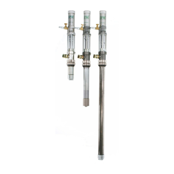
1:1 ratio transfer pump
Hide thumbs
Also See for IP-01:
- Operationing manual with parts identification (24 pages) ,
- Operation manual (34 pages) ,
- Operation manual (34 pages)

Related Manuals for IPM IP-01


Summary of Contents for IPM IP-01
- Page 1 IP-01 1:1 RATIO TRANSFER PUMP OPERATING MANUAL IPM, INC. Manufactured by International Pump Manufacturing, Inc. Covers models: IP01, IP01S, IP01-SST and IP01S-SST. Manual Number: MIP11192008...
- Page 2 Notice: All statements, information and data given herein are believed to be accurate and reliable but are presented without guarantee, warranty or responsibility of any kind expressed or implied. Statements or suggestions concerning possible use of IPM equipment are made without representation or warranty that any such use is free of patent infringement, and are not recommendations to infringe any patent.
-
Page 3: Table Of Contents
TABLE OF CONTENTS SAFETY WARNINGS INSTALLATION OPERATIONS Working principle of transfer pump (fluid section) Start-up and adjustment of the pump Shut-down procedure Daily maintenance check Disassembly procedure Assembly procedure PARTS DIAGRAMS AND PART LISTS FOR ALL PUMPS Parts drawing and parts list for Air Motor Section (All pumps) Parts drawing and parts list for IP01 (Fluid section) -
Page 4: Safety Warnings
1.0 SAFETY WARNINGS Please read and observe all warnings contained in this operations manual before any attempt to operate the equipment. Misuse of Equipment Misuse of the Equipment can cause serious injury. Use the equipment only for its intended purpose. Care should be taken to prevent over pressurization of the pump or accessories connected to it. - Page 5 Use the air bleed down valve (see installation instructions) to relieve the air pressure in the system. Relieve the fluid pressure by holding a grounded metal pail in contact with the metal part of the fluid dispense valve and slowly opening the valve. With a container ready to catch the fluid open the drain valve (see installation instructions).
- Page 6 Hazards from Fire or Explosion Hazards exist when sparks can ignite vapors or fumes from flammable or combustible materials or other hazardous conditions (explosive dusts, etc.). These sparks can be created from plugging in or unplugging an electrical supply cord. Sparks can also be created from the static electricity generated by the flow of fluid through the pump and hose.
- Page 7 FIGURE 1 Grounding the Pump: Follow these procedures for grounding the pump. Loosen the lock screw (W) to allow insertion of one end of a 12 gauge minimum size wire into the hole in the side of the lug (Z). Insert the wire (Y) and tighten the lock screw securely.
-
Page 8: Installation
2.0 INSTALLATION ½” FIGURE 2 Figure 2 depicts a typical installation provided as a guide for your reference. Select and install optional accessories required. Feel free to call your IPM representative or the IPM Technical Department for assistance. - Page 9 Mounting Configuration Install the necessary accessories in sequence using Figure 2 as a guide. An Air Control Valve (K) for Controlling air flow is required with the equipment. To minimize the risk of serious bodily injury such as splashing fluid on the skin or in the eyes or risk of injury from moving parts, install the following accessories in your system.
-
Page 10: Operations
3.0 OPERATIONS... -
Page 11: Start-Up And Adjustment Of The Pump
Start up and Adjustment of the Pump Ensure that installation is fully completed before proceeding to start up operations. Ensure that the air control valve (K) is closed. Open the bleed-type master air valve (D). Connect the quick disconnect coupler to the male fitting. Into a grounded metal container, open the dispensing valve (G) slowly. -
Page 12: Daily Maintenance Check
Daily Maintenance Check: 1. Ensure sufficient lubricant in the air lubricator. ½ 2. Keep the packing cup filled with a suitable fluid (it will keep the piston rod clean and lubricate the packing). 3. Drain the moisture trapped in the air pressure cylinder. Clean and flush the pump thoroughly with care and appropriate cleaning fluid to obtain the maximum service life of the equipment. - Page 13 3. Remove the foot valve (27), while holding the cylinder (14) with a strap wrench as shown. 4. Use snap ring pliers to remove (24) and (25). Remove ball (26) and examine for debris and/or damage. Replace as necessary. Replace Teflon o-ring (9). Re-assemble for valve (27) with ball (26), snap rings (24) and (25).
- Page 14 7. Please note that you need to loosen the jam nuts (17), and then retighten upon assembly. 8. Clamp piston valve housing (19) in vice and unscrew piston pump (23). Remove piston cup (22) and examine for damage; replace if necessary. Check piston valve (20) within the housing (19) for build up and debris.
- Page 15 Outlet Housing Tie rod Cotter pin Piston shaft Locking nut 12. From the Air Motor section 5.1, remove the cotter pin (16) and pull out the pin (17). Unscrew the displacement rod (16*) from the piston shaft (15). *The displacement rod is shown in the fluid section 5.2.
-
Page 16: Assembly Procedure
15. From fluid section, unscrew displacement rod (16) from the piston shaft (15 from section 5.1 Examine for damage due to debris build-up. Re-assemble the muffler (24), with the point of the cone up- inside the piston shaft and the displacement rod (16) to the piston shaft. 16. -
Page 17: Parts Drawing And Parts List For Air Motor Section (All Pumps)
4.0 Air Motor parts diagram and part list for all pumps 4.1 Parts Drawing for AIR MOTOR Section (all pumps) Note: Part number 12 (threads) and part number 5 require the use of Loctite-222 to help ensure they do not come undone. - Page 18 4.1 Parts list for AIR MOTOR Section (all pumps) New part Old Part Number Number Description 500100 01-172-406 Cap, cylinder 500101 01-172-404 Gasket 500103 01-178-866 Spring 500102 01-172-407 Air cylinder Plate, air 500138 01-162-729 exhaust valve 500137 01-189-210 Piston, air Spacer, valve 500140 01-181-485...
-
Page 19: Parts Drawing And Parts List For Ip01 (Fluid Section)
Parts drawing for Fluid Section of Carbon Steel Drum Pump (IP01) - Page 20 4.1 Parts list for Fluid Section of Carbon Steel Drum Pump (IP01) New Part Old Part Number Number Description 500115 01-104-541 Nut, lock, M8 500117 01-177-152 Nut, packing 500118 01-178-543CS Gland, female 500116 01-177-171 Tie rod V-packing 500119 01-177-164 (Polyethylene) 500120 01-172-385CS Gland, male...
-
Page 21: Parts Drawing And Parts List For Ip01S (Fluid Section)
Parts drawing for Fluid Section (C/Steel Stubby Pump) IP01S... - Page 22 Parts list for Fluid Section (C/Steel Stubby Pump) IP01S New Part Ref No. Number Old Part Number Description 500115 01-104-541 Nut, lock, M8 500117 01-177-152 Nut, packing 500118 01-178-543CS Gland, female 500116 01-177-171 Tie rod V-packing 500119 01-177-164 (Polyethylene) 500120 01-172-385CS Gland, male 500122...
-
Page 23: Parts Drawing And Parts List For Ip01Sst (Fluid Section)
Parts drawing for Fluid Section (IP01SST) Stainless Drum Length... - Page 24 Parts list for Fluid Section (IP01SST) Stainless Drum Length New Part Number Old Part No. Description 500115 01-104-541 Nut, lock, M8 500152 01-180-049 Nut, packing 500153 01-178-543 Gland, female (S/S) 500163 01-177-170 Tie rod V-packing 500119 01-177-164 (Polyethylene) 500154 01-172-385 Gland, male 500122 01-101-281...
-
Page 25: Parts Drawing And Parts List For Ip01S-Sst (Fluid Section)
Parts drawing for Fluid Section (IP01S-SST) Stainless Steel Stubby Pump... - Page 26 4.5 Parts list for Fluid Section (IP01S-SST) Stainless Steel Stubby Pump New Part Ref No. Number Old Part No. Description 500115 01-104-541 Nut, lock, M8 500152 01-180-049 Nut, packing 500153 01-178-543 Gland, female 500163 01-177-170 Tie rod 500119 01-177-164 V-packing 500154 01-172-385 Gland, male...
-
Page 27: Repair Kits
REPAIR KITS IP01 FLUID SECTION REPAIR KITS IP01 UHMW Repair Kit New P/N Old P/N Description Fluid Section 601006 01-215-964 Repair Kit Individual Kit Components 500153 01-178-543 Gland Female 500119 01-177-164 V- packing 500154 01-172-385 Gland Male 500132 01-177-159 Cup, Piston IP01 Teflon Repair Kit New P/N Old P/N... -
Page 28: Trouble Shooting
6.0 TROUBLE SHOOTING Problem Cause Recommended Solutions *Remove and then reattach the quick disconnect Pump does not *Air Motor stalled fitting in an effort to "re-boot" the air motor. move. Make sure pump has no air or liquid pressure. *Fluid section seized Remove air cylinder and cap from air motor. -
Page 29: Technical Specifications
7.0 TECHNICAL SPECIFICATIONS (A) Recommended Application Chart Viscosity Industry Application Range(CPS) Alcohol 0-100 0-1000 Methyl Chloride 0-200 Solvents 0-500 Paint(Latex) 100-1000 Paint(Oil base) 100-800 Sealer(Wood) 100-800 Stain(Oil base) 100-1000 Anti-Freeze 30-100 Die Lubricant 30-50 Gear Oil 200-1000 Lubricant 100-1500 Mold Release Agent 30-100 100-500 (B) Technical Specifications... - Page 31 Air Operated Fluid Pump __________________________________________ IPM’s IP-01 series of pumps are general purpose transfer pumps designed for use with a wide variety of materials. The air driven motor is designed with simplicity in mind for years of use in less than desirable conditions.
-
Page 32: Warranty And Disclaimer
The warranty does not apply or nor will IPM be liable for damage, wear, or malfunction of equipment caused by improper installation, misuse, abrasion, corrosion, negligence, accident, tampering, lack of improper maintenance, or by substitution of non-IPM parts. - Page 33 3107 142 Avenue East, Suite 106 Sumner, Washington 98390 Telephone: (253)863-2222 Fax: (253)863-2223 Website: ipmpumps.com Email: sales@ipmpumps.com Revised 10/17/2009...
Need help?
Do you have a question about the IP-01 and is the answer not in the manual?
Questions and answers