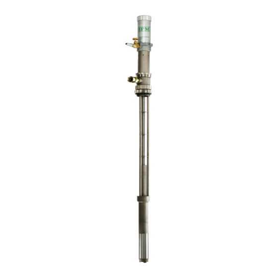
IPM IP-02 Operating Manual
2:1 ratio transfer pump
Hide thumbs
Also See for IP-02:
- Operation manual (36 pages) ,
- Operationing manual with parts identification (28 pages) ,
- Operating manual (20 pages)

Related Manuals for IPM IP-02


Summary of Contents for IPM IP-02
- Page 1 IP-02 2:1 RATIO TRANSFER PUMP OPERATING MANUAL IPM, INC. Manufactured by International Pump Manufacturing, Inc. Covers models: IP02, IP02S, IP02SST and IP02S-SST Manual Number: MIP11192008...
- Page 2 Notice: All statements, information and data given herein are believed to be accurate and reliable but are presented without guarantee, warranty or responsibility of any kind expressed or implied. Statements or suggestions concerning possible use of IPM equipment are made without representation or warranty that any such use is free of patent infringement, and are not recommendations to infringe any patent.
-
Page 3: Table Of Contents
5.1 PARTS DIAGRAM FOR AIR MOTORS (IP02/IP02S).. ……… 18 5.2 PARTS LIST FOR AIR MOTORS (IP02/IP02S) …………… 19 5.3 FLUID SECTION PARTS DIAGRAM IP02 5.4 PARTS LIST IP-02…………………………………………. 5.5 FLUID SECTION PARTS DIAGRAM IP-02SST……….. 5.6 PARTS LIST IP-02SST……………………………………. ….……. 23 5.7 FLUID SECTION PARTS DIAGRAM IP02-S.. -
Page 4: Safety Warnings
1.0 SAFETY WARNINGS Please read and observe all warnings contained in this operations manual before any attempt to operate the equipment. Misuse of Equipment Misuse of the Equipment can cause serious injury. Use the equipment only for its intended purpose. Care should be taken to prevent over pressurization of the pump or accessories connected to it. - Page 5 Use the air bleed down valve (see installation instructions) to relieve the air pressure in the system. Relieve the fluid pressure by holding a grounded metal pail in contact with the metal part of the fluid dispense valve and slowly opening the valve. With a container ready to catch the fluid open the drain valve (see installation instructions).
- Page 6 Solvent Containers: Grounding must be done according to local codes. Use metal conductive pails that are properly grounded. Grounding while Maintain conductivity by firmly holding the metal part of the dispensing, cleaning, dispensing valve to the side of a grounded metal container. or relieving: FIGURE 1 Grounding the Pump:...
-
Page 7: Installation
2.0 INSTALLATION FIGURE 2 Figure 2 depicts a typical installation provided as a guide for your reference. Select and install optional accessories required. Feel free to call an IPM representative or the IPM Technical Department for assistance. -
Page 8: Mounting Configuration
Mounting Configuration Install the necessary accessories in sequence using Figure 2 as a guide. An Air Control Valve (K) for Controlling air flow is required with the equipment. To minimize the risk of serious bodily injury such as splashing fluid on the skin or in the eyes; or risk of injury from moving parts, install the following accessories in your system. -
Page 9: Operations
3.0 OPERATION Start up and Adjustment of the Pump (Refer figure 2, page 7) Ensure that installation is fully completed before proceeding to start up operations. Ensure that the air control valve (K) is closed. Open the bleed-type master air valves (D). - Page 10 Relieve the fluid pressure by holding a grounded metal pail in contact with metal part of the fluid dispense valve (G) and slowly opening the valve. With a container ready to catch the fluid open the drain valve (G) (see installation instructions).
-
Page 11: Air Motor Disassembly
4.0 IP-02 Maintenance & Repair Section 4.1 Air Motor Disassembly Procedure 1. Follow the Procedure For Pressure Relief on page 9. It is very important to relieve all air and fluid line pressure, as well as pump pressure before proceeding to the next step or injury can occur. - Page 12 Remove the air cylinder either by hand or by using a strap wrench. Air piston assembly with the Air Cylinder removed. Place a pair of channel-lock pliers on the knurled area and a crescent wrench on the flats to remove the air piston assembly. Examine the spring in the air motor cap to ensure that it is not damaged or loose.
-
Page 13: Air Motor Assembly
4.2 Air Motor Assembly Procedure (Reference numbers come from Page 20, Air Motor Section) Assemble the Air Piston assembly (12). Includes parts (13A through 13G). The Air Exhaust Valve Plate (13E) and the screws (13A) require the use of Loctite-222 on the threads to ensure they do not vibrate loose. -
Page 14: Disassembly Lower Fluid Section
Spring must be pushed under the lip inside the cap 3. Place the conical spring (2) into the groove in the Air Cylinder Cap (10) followed by Gasket (6). Clamp the Air Motor Base in to a vice and use a strap wrench to assemble the Air Cylinder (3) and the Air Cylinder Cap to the Air Motor Base. - Page 15 Just push it in far enough to re attach the foot valve. IP-02 lower foot valve parts. On the stubby version there are ¾” female pipe threads under the Foot Valve- on the drum length IP02 there are not. Should you need to extend in to your container farther, it is recommended to install a proper Cylinder Extension Tube to keep the foot valve at the lowest possible point.
- Page 16 4.4 Attaching lower fluid assembly to the Air Motor assembly The Piston Rod is actually inside the Air Motor assembly- which has been removed so you can see more detail. Notice how the Upper Connecting Rod is being inserted at an angle. This is to ensure that the ball on the end correctly engages the slot or notch in the photo on the left.
-
Page 17: Parts Identification
5.0 PARTS IDENTIFICATION: Parts Drawing for AIR MOTOR IP-02 (Drum Length) Parts Drawing for AIR MOTOR IP02S (Stubby) 14A: Complete air motor assy. for IP02. 14B: Complete air motor assy. for IP02S... - Page 18 Parts List for AIR MOTOR IP-02 (Drum Length) Parts List for AIR MOTOR IP02S (Stubby) New Part Old Part Number Number Description 500206 02-156-698 O-ring 500284 02-157-630 SPRING, conical 500203 02-157-632 Air cylinder (IP02) 500241 02-186-565 Air cylinder (IP02S) SPRING,...
- Page 19 Parts drawing for IP-02 Fluid Section for C/Steel (Drum Length)
- Page 20 Parts List for IP-02 Fluid Section for C/Steel (Drum Length) New Part Old Part Number Number Description 700038 02-204-722 AIR MOTOR Displacement pump 700047 02-208-197 assy. (includes items 3-31) 500213 02-102-596 O-Ring, Teflon 500268 02-101-750 BALL, piston valve 500269 02-101-917...
- Page 21 Parts drawing for IP-02SST Fluid Section for S/Steel (Drum Length)
-
Page 22: Parts List Ip-02Sst
Parts List for IP-02SST Fluid Section for S/Steel (Drum Length) New Part Old Part Number Number Description 700038 02-204-722 AIR MOTOR Displacement pump 700048 02-204-724 assy. (includes items 3-31) 500213 02-102-596 O-Ring, Teflon 500268 02-101-750 BALL, piston valve 500269 02-101-917 BALL, intake valve 500221 02-161-788... - Page 23 Parts drawing for IP-02S Fluid Section for C/Steel Stubby...
- Page 24 Parts List for IP-02S Fluid Section C/Steel Stubby New Part Old Part Number Number Description 700046 02-223-953 AIR MOTOR Displacement pump 700049 02-223-955CS assy. (includes items 3-33) 500233 02-100-040 PLUG, pipe 3/8” NPT 500268 02-101-750 BALL, piston valve 500269 02-101-917 BALL, intake valve 500221 02-161-788...
- Page 25 Parts drawing for IP-02S-SST Fluid Section S/Steel Stubby...
- Page 26 5.10 Parts list for IP-02S-SST Fluid Section S/Steel Stubby New Part Old Part Number Number Description 700046 02-223-953 AIR MOTOR Displacement pump 700050 02-223-955 assy. (includes items 3-33) 500267 02-101-748 PLUG, pipe 3/8" NPT 500268 02-101-750 BALL, piston valve 500269 02-101-917 BALL, intake valve 500221...
-
Page 27: Repair Kits
6.0 Repair Kits IP02 Air Motor New Part Number Old Part Number Description 601011 02-990-053 Air Motor Repair Kit 500236 02-158-109 O-Ring 500144 02-108-358 O-Ring 500141 02-108-357 O-Ring 500206 02-156-698 O-Ring IP02 Fluid Section New Part Number Old Part Number Description 601009 02-990-051... -
Page 28: Troubleshooting
7.0 TROUBLESHOOTING Problem Causes Recommended Solutions Air supply or pressure is Increase air pressure. Check inadequate. Air lines for any restrictions in air line. restricted. Open and/or clear valve. Dispensing valve is not open or clogged. Follow pressure relief Pump does not operate. procedure to clear obstruction. -
Page 29: Technical Specifications
8.0 TECHNICAL SPECIFICATIONS (A) Recommended Application Chart Viscosity Industry Application Range(CPS) Alcohol 0-100 0-1000 Methyl Chloride 0-200 Solvents 0-500 Paint(Latex) 100-1000 Paint(Oil base) 100-800 Sealer(Wood) 100-800 Stain(Oil base) 100-1000 Anti-Freeze 30-100 Die Lubricant 30-50 Gear Oil 200-1000 Lubricant 100-1500 Mold Release Agent 30-100 100-500 (B) Technical Specifications... - Page 31 Air Operated Fluid Pump __________________________________________ IPM’s IP-02 series of pumps are specifically designed for use with difficult to handle materials. The immersed lower pump, tie tubes, and sealing bung bushing allow quick drum change without exposing the system to contamination and moisture.
-
Page 32: Warranty And Disclaimer
The warranty does not apply or nor will IPM be liable for damage, wear, or malfunction of equipment caused by improper installation, misuse, abrasion, corrosion, negligence, accident, tampering, lack of improper maintenance, or by substitution of non-IPM parts. - Page 33 Avenue East, Suite 106 3107 142 Sumner, Washington 98390 Telephone: (253) 863-2222 Fax: (253) 863-2223 Website: ipmpumps.com Email: sales@ipmpumps.com Revised 10/17/2009...
Need help?
Do you have a question about the IP-02 and is the answer not in the manual?
Questions and answers