IPM IP02 Series Operationing Manual With Parts Identification
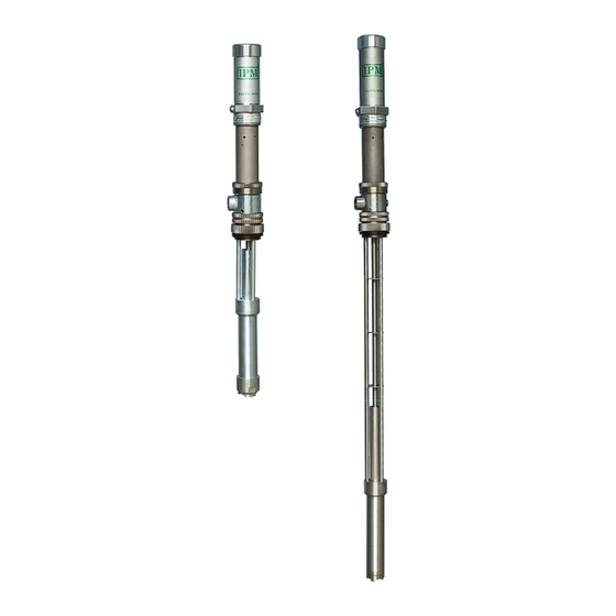
2:1 ratio transfer pump
Hide thumbs
Also See for IP02 Series:
- Operation manual (36 pages) ,
- Operating manual (33 pages) ,
- Operation manual (36 pages)
Table of Contents
Advertisement
Quick Links
Download this manual
See also:
Operating Manual
Advertisement
Table of Contents

Related Manuals for IPM IP02 Series


Summary of Contents for IPM IP02 Series
-
Page 1: Parts Identification
810201,810202,810203,810204 IP02 SERIES 2:1 RATIO TRANSFER PUMP OPERATIONING MANUAL WITH PARTS IDENTIFICATION IPM, INC. Manufactured by International Pump Manufacturing, Inc. - Page 2 Notice: All statements, information and data given herein are believed to be accurate and reliable but are presented without guarantee, warranty or responsibility of any kind expressed or implied. Statements or suggestions concerning possible use of IPM equipment are made without representation or warranty that any such use is free of patent infringement, and are not recommendations to infringe any...
-
Page 3: Table Of Contents
TABLE OF CONTENTS SAFETY WARNINGS INSTALLATION Installation procedures OPERATION Start up and adjustment of transfer pump Shut down procedure MAINTENANCE AND REPAIR Air motor section disassembly Air motor section assembly Fluid section disassembly Securing the fluid section to the air motor section PARTS IDENTIFICATION Parts drawing for air motor section of 810201,810203 Parts drawing for fluid section of 810201... -
Page 4: Safety Warnings
Use only IPM designated parts for re-building or repairing this equipment. Use the pump only with compatible fluids. Improper use of this equipment could result in fluid being sprayed on the skin or in the eyes of user, serious bodily injury, property damage, fire or explosion. - Page 5 Pressurized hoses Because the hoses are pressurized they can present a danger should the fluid escape due to damage, worn parts or general miss-use. Escaping fluid can splash or spray operator, causing serious bodily injury and/or damage to equipment and property. Ensure that the hoses do not leak or rupture due to wear, misuse or damage.
- Page 6 If the pump is being used to supply a circulating system, allow the solvent to circulate through the entire system for at least 30 minutes every 48 hours or more often if necessary to prevent settling and solidification of chemicals. Lubricate the throat packing frequently, when you are pumping a non-lubricating fluid or shutting down for more than one day Shut down &...
- Page 7 Air compressor: Follow the grounding procedures as recommended by the compressor manufacturer. Air hoses: Always use grounded air hoses. Fluid container used to Grounding must be done according to local electrical supply the system: codes. Pump: Follow the procedures referred to in Figure A (page 6). Fluid Hoses: Always use grounded fluid hoses.
-
Page 8: Installation
2.0 INSTALLATION Figure B depicts only a typical installation providing a guide for your reference but many other installation methods can be used based on your specific application. Some parts shown are not included but are sold separately. Feel free to call your Local Distributor for assistance. -
Page 9: Installation Procedures
Install the necessary accessories in sequence using Figure B (page 8) as a guide. An air control valve (IPM part #601805) for controlling air flow is required. To minimize the risk of serious injury such as splashing/spraying chemicals on the skin, in the eyes or injury from moving parts, install the following accessories in your system. -
Page 10: Operation
3.0 OPERATION 3.1 Start up and adjustment of transfer pump Ensure that the air control valve is closed then open the bleed-type master air valve. Connect the quick disconnect coupler to the male fitting. For safety, open the dispensing valve slowly, then drain fluid into a grounded metal container. -
Page 11: Maintenance And Repair
4.0 MAINTENANCE AND REPAIR Air motor section disassembly 1. Follow the Procedure for Pressure Relief (page 5). It is very important to relieve all air and fluid line pressure as well as pump pressure before proceeding to the next step or injury can occur. 2. - Page 12 Remove the air cylinder either by hand or by using a strap wrench. Air motor assembly and piston rod with the air cylinder removed. Place a pair of channel-lock pliers on the knurled area of the exhaust valve plate and a crescent wrench on the flats to remove the air piston assembly.
-
Page 13: Air Motor Section Assembly
4.2 Air motor section assembly Assemble the air motor assembly in reverse order from above procedure. Ensure all parts shown in illustration below are included and in operable shape. The air exhaust valve plate and socket head screws require the use of threadlocker on the threads to ensure they do not vibrate loose. -
Page 14: Fluid Section Disassembly
3. Insert the conical spring into the machined groove in the air cylinder cap followed by the square cut gasket. Clamp the air motor base into a vice, using a strap wrench to re-assemble the air cylinder and air cylinder cap to the air motor base. Hand-tighten only the air cylinder cap so as not to damage the gasket. - Page 15 Breakdown of internal foot valve. Internal foot valve disassembled. Clean, inspect or replace if necessary these components before re-assembly. Use threadlocker when re-installing. After the lower piston rod is inspected and proper parts replaced/cleaned as needed, inspect the lower body assembly and make sure that they are also clean and free from any scratches.
-
Page 16: Securing The Fluid Section To The Air Motor Section
4.4 Securing the fluid section to the air motor section The piston rod is actually inside the air motor assembly- which has been removed in the above illustration so you can see more detail. Notice how the upper connecting rod is being inserted at an angle. This is to ensure that the ball on the end correctly engages the keyway slot in the photo on the left. -
Page 17: Parts Identification
5.0 PARTS IDENTIFICATION Parts drawing for air motor section Pump # 810201、 、 、 、 810203 *Part number 500142 (threads) and part number 500138 require the Loctite 243 to help ensure they do not come undone. **Part number 700027 (threads) require the use the Loctite 243 to help ensure they do not come undone. -
Page 18: Parts Drawing For Fluid Section Of 810201
5.2 Parts drawing for fluid section Pump # 810201... -
Page 19: Parts Drawing For Fluid Section Of 810203
5.3 Parts drawing for fluid section Pump # 810203... -
Page 20: Parts Drawing For Air Motor Section Of 810202,810204
5.4 Parts drawing for air motor section Pump # 810202、 、 、 、 810204 *Part number 500142 (threads) and part number 500138 require the Loctite 243 to help ensure they do not come undone. **Part number 700027 (threads) require the use the Loctite 243 to help ensure they do not come undone. -
Page 21: Parts Drawing For Fluid Section Of 810202
5.5 Parts drawing for fluid section Pump # 810202... -
Page 22: Parts Drawing For Fluid Section Of 810204
5.6 Parts drawing for fluid section Pump # 810204... -
Page 23: Repair Kits
6.0 REPAIR KITS IP02 Series – 2:1 pump repair kits 601011 Air motor section repair kit Fits: 810201, 810202, 810203, 810204 Components include Part # Description 500141 O-ring 500144 O-ring 500206 O-ring 500236 Gasket 601013 Fluid section repair kit Fits: 810201, 810202, 810203, 810204... -
Page 24: Troubleshooting
7.0 TROUBLESHOOTING Problem Causes Recommended Solutions Air supply or pressure is Increase air pressure. Check inadequate. Air lines restricted. for any restrictions in air line. Dispensing valve is not open Open and/or clear valve. or clogged. Follow pressure relief Clogged fluid lines, valves, Pump does not operate. -
Page 25: Technical Specifications
8.0 TECHNICAL SPECIFICATIONS Pressure Ratio Fluid Flow At 120 CPM 3.2 gpm (11.9 lpm) Maximum Fluid Pressure 360 psi (24.8 bar) Air Input Pressure Range 30-180 psi (2-12.4 bar) Air Inlet Size 1/4” NPT (F) Fluid Outlet Size (Stubby) 3/4” NPT (F) Weight Stubby / Drum 15.8 lbs (7.2kg) / 19.8 lbs (9kg) Packing / Seals... - Page 26 Performance How to Read Performance 1. Locate required flow along bottom edge of chart. 1. Locate fluid flow along bottom edge of chart. 2. Follow vertically to bold line for input air pressure. 2. Follow vertically to bold line for input air pressure. 3.
-
Page 27: Warranty And Disclaimer
IPM distributor to the original purchaser. IPM will at its discretion repair or replace any part of the equipment proven to be defective. This warranty applies only when the equipment is used for the intended purpose and has been installed, operated and maintained in accordance with the written recommendations. - Page 28 3107 142 Avenue East Suite 106 Sumner, WA 98390 U.S.A. TEL: (253) 863 2222 FAX: (253) 863 2223 Website : www.ipmpumps.com Updated Aug 2017...
Need help?
Do you have a question about the IP02 Series and is the answer not in the manual?
Questions and answers