Table of Contents
Advertisement
Quick Links
Target National Account
EnergyX
System
R
Factory Installed Energy Recovery
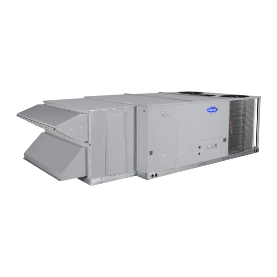
48/50HC WeatherMasterr Commercial Rooftop Units
12.5 Nominal Ton Units
with Puronr (R -- 410A) Refrigerant
and I/O Flex 6126 Controls
Supplemental Installation Instructions
This document is a supplemental installation instruction for Target rooftop units
with the EnergyX factory installed Energy Recovery Ventilator. It is to be used with
the base HC 12.5 Ton rooftop unit Installation Instructions.
NOTE: Read the entire instruction manual before starting
the installation
TABLE OF CONTENTS
. . . . . . . . . . . . . . . . . . . . . . . . . . . . . . . . . . . .
. . . . . . . . . . . . . . . . . . . . . . . . . . . . . . .
. . . . . . . . . . . . . . . . . . . . . . . . . . . . .
. . . . . . . . . . . . . . . . . . . . . . . . . . . . . . . . .
. . . . . . . . . . . . . . . . . . . . . . . . . . . . . . .
. . . . . . . . . . . . . . . . . . . . . . . . . . . . .
. . . . . . . . . . . . . . . . . . . . . . . . . . . . . . . . . .
. . . . . . . . . . . . . . . . . . . . . . . . . .
. . . . . . . . . . . . . . . . . . . . . . . . . . . . . . . . . . . . .
. . . . . . . . . . . . . . . . . . . . . . . . . . . .
. . . . . . . . . . . . . . . . . . . . . . . . . . . . . . . .
. . . . . . . . . . . . . . . . . . . . . . . . .
Off Mode -
. . . . . . . . . . . . . . . . . . . . . . . . . . . . .
. . . . . . . . . . . . . . . . . . . . . . . . . . . . .
. . . . . . . . . . . . . . . . . . . . . . . . . .
. . . . . . . . . . . . . . . . . . . .
. . . . . . . . . . . . . . .
. . . . . . . . . . . . .
. . . . . . . . . . . . . . . . . . . .
. . . . . . . . . . . . . . . . . .
. . . . . . . . . . . . . . . . . .
. . . . . . . . . . . . . . . . . .
. . . . . . . . . . . . . . . . . . .
. . . . . . . . . . . . . . . . . . . . . . .
. . . . . . . . . . . . . . . . . . . . .
. . . . . . . . . . . . . . . . . . . . . . .
. . . . . . . . . . . . . . . . . . . . .
2
3
5
5
5
5
5
5
6
8
8
. . . . . . . . . . . . . . . . . . . . . . . . . . . . . . . . . . .
9
9
. . . . . . . . . . . . . . . . . . . . . . . . . . . . . . . . . . . .
9
9
. . . . . . . . . . . . . . . . . . . . . . . . . . . . . . . . .
9
9
9
9
9
9
13
14
14
14
14
14
. . . . . . . . . . . . . . . . . . . . . .
. . . . . . . . . . . . . . . . . . . . . . . . . . . .
. . . . . . . . . . . . . . . . . . . . . . . . .
. . . . . . . . . . . . . . . . . . . . . .
. . . . . . . . . . . . . . . . .
. . . . . . . . . . . . . . . . . .
. . . . . . . . . . . . . . .
. . . . . . . . . . . . . . .
. . . . . . . . . . . . . . . . . . . . . . . . . . . .
. . . . . . . . . . . . . . . . . . . . . . . . . . . .
. . . . . . . . . . . . . . . . . . . . . . .
. . . . . . . . . . .
. . . . . . . . . .
. . . . . . . . . . . . . . . . . .
. . . . . . . . . . . . . . . . .
. . . . . . . . . . . . . . . . . . . .
. . . . . . . . . . . . . . . . . . . . . .
. . . . . . . . . . . . . . . . . . . .
. . . . . . . . .
. . . . . . . . . . .
. . . . . . . . . .
. . . . . . . . . . . . . . . . . . .
. . . . . . . . . . . . . . . . . . .
. . . . . . . .
. . . . . . . . . . . . . . . . . . . .
. . . . . . . . . . . . . . . . . . . . . . .
14
15
15
15
15
15
15
18
19
19
19
19
19
20
20
20
20
20
20
20
20
21
21
. .
22
23
23
24
24
24
26
Advertisement
Table of Contents

Related Manuals for Carrier EnergyX 48HC


Summary of Contents for Carrier EnergyX 48HC
-
Page 1: Table Of Contents
Target National Account EnergyX System Factory Installed Energy Recovery 48/50HC WeatherMasterr Commercial Rooftop Units 12.5 Nominal Ton Units with Puronr (R -- 410A) Refrigerant and I/O Flex 6126 Controls Supplemental Installation Instructions This document is a supplemental installation instruction for Target rooftop units with the EnergyX factory installed Energy Recovery Ventilator. -
Page 2: Safety Considerations
Appendix D — I/O Flex 6126 Controller ..DANGER identifies the most serious hazards which will Appendix E — Carrier BACview/Virtual BAC view result in severe personal injury or death. WARNING Commissioning . -
Page 3: General
GENERAL WARNING This publication contains Installation, Start- - Up, Controls, ELECTRICAL SHOCK HAZARD Operation, Troubleshooting and Service information for the EnergyX Energy Recovery System, factory installed Failure to follow this warning could cause personal on a 48/50HC (12.5 nominal ton) rooftop unit. This injury or death. - Page 4 Physical Data Table 1 – Physical Data Model 48/50HC Size 14 (12.5 Ton) EnergyX Unit Type Modulating Air Flow Capability ERV WHEEL OA (CFM) 1,875 ERV WHEEL EA (CFM) 1,550 ENERGY RECOVERY WHEEL TYPE Enthalpy Lightweight Polymer with Silica Gel Desiccant Coating MODEL (AirXchange) ERC-3019C SIZE (Dia.
-
Page 5: Installation
INSTALLATION An EnergyX unit is installed as a single piece unit. To install an EnergyX unit, follow the base rooftop unit installation instructions with the following exceptions and additions: Install Roofcurb SCREW LOCATION TYPICAL, 8-PLACES RTU HOLD-DOWN BRACKET Vertical Airflow Configurations — The EnergyX unit uses the standard HC base unit roofcurb. -
Page 6: Positioning
Follow all local codes for proper clearances – the local code requirements take precedence over any clearance listed in this document. Contact your local Carrier representative for clearance obstructions and any potential resulting affect on unit warranty. Follow all other curb, rigging, and positioning installation... - Page 7 C13081 LOCATION DIMENSION CONDITION 48--- in (1219 mm) Unit disconnect is mounted on panel 18--- in (457 mm) No disconnect, convenience outlet option 18--- in (457) mm Recommended service clearance 12--- in (305 mm) Minimum clearance 36--- in (914 mm) Recommended service clearance 54--- in (1372 mm) Recommended service clearance...
-
Page 8: Outside Air Hood Installation
Outside Air Hood Installation Exhaust Air Hood Installation 1. Gasket the entire perimeter of the outside air hood 1. Gasket the entire perimeter of the exhaust air hood along the flange using gasket provided. along the flange using gasket provided. 2. -
Page 9: Make Electrical Connections
Make Electrical Connections base Controls book. Fill in all blank data entries that are applicable to the exact unit being installed. The ERV model and serial numbers are printed in the ERV control See the base unit name plate for the ETL certified box. - Page 10 Table 2 – Inputs - - Points the ERV Read Value Expanded Text Range Units Default Function NVO_MODE nvoUnitStatus.mode xxxx Determine what mode RTU is in OCCUPIED Currently Occupied No/Yes Determine if RTU is occupied IDFSTATE Indoor Fan State Off/On Determine if the RTU indoor fan is running FANSPEED...
- Page 11 Table 3 – Configurations - - ERV Configurations Read Value Expanded Text Range Units Default Function OAU_TYPE Outdoor Air Unit Type 0=No OAU 0: no FIOP Defines what kind of OAU is 1=ERV Module 1: FIOP EXv2 installed 2=Economizer* 3=Pwr Exhaust 4=OA Monitor 5=100% OA unit 6=EXv1 ERV...
- Page 12 Table 4 – Status Points - - ERV Writes these Values Value Expanded Text Range Units Function OAU_RUN OAU System Run State 1=AUTO High level ERV state 2=OFF 3=TEST OAU_MODE OAU Operating Mode 0=Off ERV’s current operating mode 1=ERV (DCV) 2=Free Cooling* 3=OA Tempering 4=Defrost...
-
Page 13: 12.5 Ton Modulating Erv
12.5 Ton Modulating ERV control ventilation (DCV) operation. The modulating ERV will operate based on occupancy and the rooftop’s The modulating ERV is an intelligent ERV with variable operating mode, the following sections explain operation speed fan motors. The ERV can provide a variety of in detail. -
Page 14: Occupancy
Occupancy DCV ERV Mode will be active when the rooftop mode is Heating, Cooling, Fan Only, or Dehumidification and the ERV is occupied. The ERV will not be allowed to run unless it is determined to be occupied. The ERV monitors the When in DCV ERV mode wheel will be rotating. -
Page 15: On- -Board Pressure Transducers
Table 5 – Transducer/Voltage vs. Pressure S Programmed occupancy schedule. Rooftop Unoccupied S Rooftop indoor fan is off. Pressure (inWC) Voltage (vDC) 2” transducer 5” transducer S The airflow sensor tubing connected to the incorrect <=--- 0.26 high/low sensor ports in the outside air. 0.12 0.28 Wheel Status (Option) —... -
Page 18: Energyx Control Board (Excb)
EnergyX Control Board (EXCB) inputs from transducers and discrete inputs. See Options and Accessories section. The EXCB has relay analog outputs, and is equipped with a LCD screen. The EXCB has a reset See Fig. 9 and Table 7. button that is used to force all the outputs and reset The EXCB board is the muscle of the ERV control system. -
Page 19: Enthalpy Wheel
Table 7 – EXCB Input/Output Connections TYPE OF CONNECTION POINT DESCRIPTION SENSOR LOCATION Input/Output Input/Output PIN NUMBER Download Both Communication Power from TRANS Control box Input 24VAC J3, 1--- 2 Power to Relays Low voltage control box Output 24VAC J4, 1 Wheel Rotation Sensor Attached to scoop Input... -
Page 20: Service & Maintenance
SERVICE & MAINTENANCE (based on filter manufacture recommendation or filter status alarm indication). Refer to Table 1 for type and size Refer to base unit’s Service manual for base unit service and of filters. maintenance. This section contains service and maintenance for just the ERV unit. -
Page 21: Wheel And Segment Removal/Installation
4. Adjust the seal towards wheel surface until a slight friction on the feeder gauge (paper) is detected while moving the gauge along the length of the spoke. 5. Re- - tighten adjustment screws and re- - check clearance with the feeder gauge. Hammer used as a “stop”... -
Page 22: Whole Wheel Removal/Installation (36" Wheels)
NOTE: The face of the segment, with the imbedded stiffener Whole Wheel Removal/Installation (vertical support between nose and rim end of segment) must (30” wheel) face the motor side of the cassette. See Fig. 14. These wheels include the shaft and are secured to two wheel Imbedded Stiffeners support beams by two flange bearings with locking collars. -
Page 23: Outside Air And Exhaust Hood Removal
Outside Air and Exhaust Air Hood Removal due to the gasket applied from original installation. Take care not to damage the gasket. If damage occurs use Outside Air Hood Removal equivalent gasket to replace before reattaching the hood. 3. Disconnect the green (HIGH) and yellow (LOW) 1. -
Page 24: Exhaust Air Hood Removal
C13027 Fig. 17 - - Exhaust Air Hood Removal Exhaust Air Hood Removal 4. Remove the fasteners at each corner of the outside air fan that secure the outside air fan front panel to the 1. Turn off, lockout and tag- - out electrical power to unit. dividing wall by access through the hood opening of 2. - Page 25 Outside Air Fan Assembly, see Detail A Detail “A” - Outside Air Fan Assembly Remove Fasteners: 4 - Places Remove Bolts: 4 - Places C13028 Fig. 18 - - Remove Fasteners from Corners of Outside Air Fan Assemble C13029 Fig. 19 - - Outside Air Fan Removal...
-
Page 26: Exhaust Fan Removal
Exhaust Fan Removal the dividing wall by access through the door of the unit. See Fig. 20. 1. Turn off, lockout and tag- - out electrical power to unit. 5. Disconnect connectors PL120 and PL122 as well as the power wires for the exhaust fan motor from the wiring 2. - Page 27 Exhaust Fan Assembly C13031 Fig. 21 - - Exhaust Fan Assembly - - Removal...
-
Page 28: Appendix
Table 14 - - 50HC with Electric Heat, ERV and 2- - Speed Indoor Fan Option Table 15 - - 50HC with Electric Heat, ERV, Factory- - Installed HACR Breaker and 2- - Speed Indoor Fan Option Appendix D — I/O Flex 6126 Installation Guide Appendix E — Carrier BACview/Virtual BACview Commissioning... -
Page 33: Appendix B - Exhaust Fan Performance
(one for exhaust air, one for return air) contact your The exhaust fan in the Modulated Volume EnergyX unit Carrier Sales Engineer for additional guidance prior to will assist the rooftop unit fan in pulling air through the specification or ordering. - Page 46 Legend and Notes for Tables 8 - - 15 LEGEND: Example: Supply voltage is 230-3-60 BRKR --- Circuit breaker AB = 224 v --- Convenient outlet BC = 231 v DISC --- Disconnect AC = 226 v --- Full load amps --- Indoor fan motor --- Locked rotor amps (224 + 231 + 226)
-
Page 47: Appendix D - I/O Flex 6126 Controller
APPENDIX D — I/O FLEX 6126 CONTROLLER General memory, and removable screw terminals for I/O connections. This appendix details the installation and configuration of The I/O Flex 6126 controller is factory- - mounted in the the I/O Flex 6126 into the Building Automation System 48/50HC unit’s main control box, to the left of the CTB (BAS). - Page 48 Specifications Driver drv_ioflex Maximum number of control programs* Maximum Number of 1000 BACnet objects* * Depends on available memory Power 24 Vac 10%, 50--- 60 Hz 20 VA power consumption (26 VA with BACview attached) 26 Vdc (25 V min, 30 V max) Single Class 2 source only, 100 VA or less Comm Ports Port 1:...
- Page 49 C13649 NOTE: Economizer not available for Target units equipped with ERV Fig. 31 - - Wiring Diagram - - 48HCD*14 with I/O Flex 6126 Controller...
- Page 50 C13650 NOTE: Economizer not available for Target units equipped with ERV Fig. 32 - - Wiring Diagram - - 50HC*14 with I/O Flex 6126 Controller...
- Page 51 To Address the I/O Flex 6126 — To Wire for Power — The I/O Flex 6126’s two rotary switches determine the I/O CAUTION Flex 6126’s MAC address when it is place on the BACnet/ARC156 or BACnet MS/TP network. The rotary EQUIPMENT PERFORMANCE HAZARD switches define the MAC address portion of the device’s BACnet address, which is composed of the network...
- Page 52 Local Access Wiring an RS Room Sensor to the I/O Flex 6126 To Communicate Through the Local Access Port The I/O Flex 6126 supports up to 5 RS sensors on its BACview/RS sensor port. Use a computer and a USB Link Kit to communicate locally with the I/O Flex 6126 to download or to troubleshoot.
- Page 53 Troubleshooting If you have problems wiring or addressing the I/O Flex 6126, contact OEMCtrl Technical Support. Communication LED’s The LED’s indicate if the I/O Flex 6126 controller is speaking to the devices on the network. The LED’s should reflect communication traffic based on the baud rate set. The higher the baud rate the more solid the LED’s become.
- Page 54 Compliance FCC Compliance CE Compliance This equipment has been tested and found to comply with WARNING the limits for a Class A digital device, pursuant to Part 15 of the FCC Rules. These limits are designed to provide RADIO INTERFERENCE HAZARD reasonable protection against harmful interference when the equipment is operated in a commercial environment.
-
Page 55: Appendix E - Carrier Bacview/Virtual Bac View Commissioning
APPENDIX E — CARRIER BACview / VIRTUAL BACview COMMISSIONING This appendix shows screen captures from the Virtual If you want to simulate the handheld BACview BACview software, however the procedure is the same performance, leave the Row Count value set to 4 as that is regardless of which method of connection is utilized. - Page 56 Press any key and you will see the HOME screen as Select HOME to go back to the main menu or TEST pictured in Fig. 37. MODE to go to HVAC TEST. If you pick TEST MODE, the screen shown in Fig. 39 appears.
- Page 57 C12806 C12808 Fig. 41 - - Value Changed (OA DAMPER POS) Fig. 43 - - Initial ERV Test Screen When you are done testing the outputs, change the TURN TEST MODE ON variable to OFF and click ENTER to turn off the test mode and put the RTU in AUTO mode (see Fig.
- Page 58 Catalog No: TAR ---ERV1---04SI Copyright 2013 Carrier Corp. D 7310 W. Morris St. D Indianapolis, IN 46231 Edition Date: 08/13 Manufacturer reserves the right to change, at any time, specifications and designs without notice and without obligations. Replaces: TAR--- ERV1--- 01SI...
- Page 59 ENERGYX UNIT START-UP CHECKLIST (To be used in conjunction with base Rooftop Unit Start- -Up Checklist. Remove and Store in Job File) RTU MODEL NO.: RTU SERIAL NO.: ERV MODEL NO.: ERV SERIAL NO.: DATE: TECHNICIAN: PRE-START-UP (insert checkmark in box as each item is completed) j VERIFY THAT ALL PACKAGING MATERIALS HAVE BEEN REMOVED FROM UNIT j VERIFY INSTALLATION OF OUTDOOR AIR HOODS j CHECK THAT AIR FILTERS ARE CLEAN AND IN PLACE ON SUPPLY AND EXHAUST OF ERV WHEEL...
- Page 60 Catalog No: TAR ---ERV1---04SI Copyright 2013 Carrier Corp. D 7310 W. Morris St. D Indianapolis, IN 46231 Edition Date: 08/13 Manufacturer reserves the right to change, at any time, specifications and designs without notice and without obligations. Replaces: TAR--- ERV1--- 01Si...
Need help?
Do you have a question about the EnergyX 48HC and is the answer not in the manual?
Questions and answers