Carrier 48HC Installation Instructions Manual
Single package rooftop gas heating/electric cooling unit with puronr (r-410a) refrigerant sizes: 04, 05, 06
Hide thumbs
Also See for 48HC:
- Installation instructions manual (52 pages) ,
- User's information manual (12 pages) ,
- Installation instructions (2 pages)
Table of Contents
Advertisement
Quick Links
48HC
Single Package Rooftop
Gas Heating/Electric Cooling Unit
with Puronr (R---410A) Refrigerant
Sizes: 04, 05, 06
NOTE: Read the entire instruction manual before starting
the installation
TABLE OF CONTENTS
. . . . . . . . . . . . . . . . . . . . . . . . . . . . . . .
. . . . . . . . . . . . . . . . . . . . . . . . . . . . . . . .
. . . . . . . . . . . . . . . . . . . . . . . . . . . . . . .
. . . . . . . . . . . . . . . . . . . . . . . . . . .
. . . . . . . . . . . . . . . . . . . . . . . . . .
. . . . . . . . . . . . . . . . . . . . . . . . .
. . . . . . . . . . . . . . . . . . . . . . . .
Installation Instructions
. . . . . . . . . . . . . . . . . . . .
. . . . . . . . . . . . . . . . . .
. . . . . .
. . . . . . . . . . . . . . . . . . . . .
. . . . . . . . . . . . . . . . . . . . . .
. . . . . . . . . . . . . . . . . . . .
. . . . . . . . . . . . . . . . . . .
. . . . . . . . . . .
. . . . . . . . . . . . . .
. . . . . . . . . . . . . . . .
. . . . . . . . . . . . . . . . . . . . .
. . . . . . . . . . . . . . . . . . . . . . .
. . . . . . . . . . . . . . .
. .
. . . . .
. . . . . . . . . .
. . . . . . . . . . . . . . . . . . . .
. . . . . . . . . . . . . . . . . . . .
. .
. . . . . . . . . . .
. . . . . . . . . . . . .
2
. . . . . . . . . . . . . . . . . . . . . . . . . . . . . . . . . .
6
6
6
6
7
7
7
7
7
Low Ambient Control (Factory Option
7
7
7
7
9
9
10
.
10
10
10
11
11
12
12
13
15
15
15
16
. . . . . . . . . . . . .
. . . . . . . . . . . . . . . . . . . . . . . . . . . . . . . .
. . . . . . . . . . . . . . . . . . . . . . .
. . . . . . . . . . . . . . . . . . . .
. . . . . . . . . . . . . . . . . . . . . . .
. . . . . . . . . . . . . . . . . . . . . . . . . . . . . . .
. . . . . . . . . . . . . . . . . . .
. . . . . . . . . . . . . . . . . . . . . . . .
. . . . . . . . . . . . . . .
. . . . . . . . . . . . . . . . . . . . . . . . . . . . .
. . . . . . . . . . . . . . . . . . . . . . . . . .
. . . . . . . . . . . . . . . . . . . . . . . . . . . .
. . . . . . . . . . . . . . . . . . . . . . .
. . . . . . . . . . . . . . . . . . . . . . . .
. . . . . . . . . . . . .
2
. . . . . . . . . . . . . . . . .
. . . . . . . . . . . . . . . . . . . .
. . . . . . . . . . . . . . . . . . . . . . . .
. . . . . . . . . . . . . . . . . . .
. . . . . . . . . . . . . . . . . . .
. . . . . . . . . . . . . . . . . . . . .
. . . . . . . . . . . . . . . . . .
. . . . . . . . . . . . . . . . . . .
17
17
18
19
19
. . . . . . . . .
20
20
20
. . . . . . .
20
20
. . . . . . . . . .
21
. . . . . . . .
21
. . . . . . . . . .
23
23
28
. . . . . . . . .
31
. . . . . . .
31
31
31
33
33
. . . . . .
33
34
34
34
35
. . . . . . . . .
35
36
36
36
36
36
38
. . . . . . . . .
41
Advertisement
Table of Contents

Related Manuals for Carrier 48HC


Summary of Contents for Carrier 48HC
-
Page 1: Table Of Contents
48HC Single Package Rooftop Gas Heating/Electric Cooling Unit with Puronr (R---410A) Refrigerant Sizes: 04, 05, 06 Installation Instructions NOTE: Read the entire instruction manual before starting Units without Factory- - Installed the installation Non- - Fused Disconnect or HACR ... . . -
Page 2: Safety Considerations
Outdoor Air Temperature (OAT) Sensor ..WARNING EconoMi$er2 ......Field Connections . - Page 3 Q = E-coat Al/Cu - E-coat Al/Cu — Louvered Hail Guard R = Cu/Cu - Al/Cu — Louvered Hail Guard S = Cu/Cu - Cu/Cu — Louvered Hail Guard C12246 Fig. 1 - - 48HC 04- - 06 Model Number Nomenclature (Example)
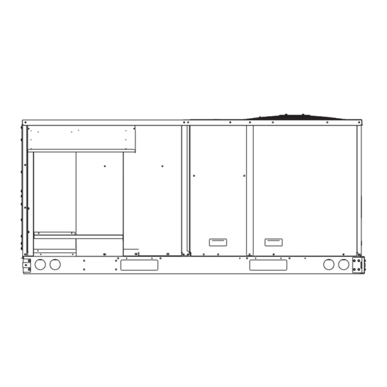
- Page 4 Vertical Connections / Economizer Horizontal Connections / Economizer C12227 Fig. 2 - - Unit Dimensional Drawing...
- Page 5 C12248 Fig. 2 - - Unit Dimensional Drawing (cont.) C08337 LOCATION DIMENSION CONDITION 48--- in (1219 mm) Unit disconnect is mounted on panel 18--- in (457 mm) No disconnect, convenience outlet option 18--- in (457) mm Recommended service clearance 12--- in (305 mm) Minimum clearance 40--- in (1067 mm) Surface behind servicer is grounded (e.g., metal, masonry wall)
-
Page 6: Installation
Do not install unit in an indoor location. Do not locate air requirements. Unit operating weight is shown in Table 1. inlets near exhaust vents or other sources of contaminated Table 1 – Operating Weights UNITS LB (KG) 48HC** Base Unit 505 (229) 590 (268) 600 (272) -
Page 7: Step 2 - Plan For Sequence Of Unit Installation
Step 2 — Plan for Sequence of Unit Installation Step 4 — Provide Unit Support The support method used for this unit will dictate different Roof Curb Mount — sequences for the steps of unit installation. For example, Accessory roof curb details and dimensions are shown in on curb- - mounted units, some accessories must be Fig. - Page 8 1’-2” ” [19] CRBTMPWR001A01 CRRFCURB001A01 [356] 1’-9 ” 1’-4” ” ” [19] ” [12.7] ” [12.7] 48HC**04-06 [551] [406] [44.5] 2’-0” ” [12.7] CRBTMPWR003A01 CRRFCURB002A01 [610] NOTES: 1. Roof curb accessory is shipped disassembled. 2. Insulated panels. 3. Dimensions in [ ] are in millimeters.
-
Page 9: Step 5 - Field Fabricate Ductwork
(914-1371) BEFORE PLACING UNIT ON ROOF CURB. SPREADER BARS DUCT END "C" "A" SEE DETAIL "A" C11292 DIMENSIONS MAX WEIGHT UNIT 48HC --- A04 74.5 1890 38.0 33.5 48HC --- A05 74.5 1890 38.0 41.5 1055 48HC --- A06 74.5 1890 37.5... -
Page 10: Positioning On Curb
Positioning on Curb — Position unit on roof curb so that the following clearances are maintained: in. (6.4 mm) clearance between the roof curb and the base rail inside the front and rear, 0.0 in. clearance between the roof curb and the base rail inside on the duct end of the unit. -
Page 11: Economizer Hood And Two- - Position Hood
PANEL Hood Parts INDOOR COIL ACCESS PANEL LEFT Plastic Tie Wrap HOOD SCREW Qty (2) SIDE 19 1/16” (483mm) 33 3/8” Screws for Metal Tray (848mm) Qty (2) HOOD DIVIDER C08639 C06026 Fig. 11 - - Economizer Hood Construction Fig. 9 - - Economizer and Two- - Position Damper Hood Parts Location 3. -
Page 12: Step 10 - Install Flue Hood
Fig. 14. Table 2 – Natural Gas Supply Line Pressure Ranges UNIT MODEL UNIT SIZE 4.0 in. wg 13.0 in. wg 48HC** 04, 05, 06 (996 Pa) (3240 Pa) 48HCF* 5.0 in. wg 13.0 in. wg... -
Page 13: Factory- - Option Thru- - Base Connections (Gas Connections)
9” MINIMUM CLEARANCE FOR PANEL REMOVAL REGULATOR MANUAL GAS SHUTOFF VALVE BASE UNIT 48” MINIMUM DRIP LEG PER NFGC BASE RAIL BRASS FITTING SUPPORT FIELD-FABRICATED EMBOSSMENT ROOF FOR 3-6 TON UNITS BRACKET SUPPORT CURB FROM C08016 LEGEND Fig. 17 - - Gas Line Piping for 3 to 6 Ton Units Only NFGC –... - Page 14 4. Pressure- - test all gas piping in accordance with local and national plumbing and gas codes before connect- ing piping to unit. 9” (229mm) min NOTE: Pressure test the gas supply system after the gas supply piping is connected to the gas valve. The supply Burner piping must be disconnected from the gas valve during the Access...
-
Page 15: Step 12 - Install External Condensate Trap And Line
Step 12 — Install External Condensate Trap Step 13 — Make Electrical Connections and Line WARNING The unit has one -in. condensate drain connection on the end of the condensate pan and an alternate connection ELECTRICAL SHOCK HAZARD on the bottom. See Fig. 22. Unit airflow configuration does not determine which drain connection to use. -
Page 16: Units With Factory- - Installed
Units Without Single Point Box, Disconnect or HACR Option 1-ph Belt Drive IFM Direct Drive IFM Equip GR Lug Equip GR Lug Disconnect Disconnect 208/230-1-60 Ground Ground (GR) (GR) 208/230-3-60 460-3-60 575-3-60 C12278 Fig. 26 - - Location of Non- - Fused Disconnect Enclosure Units With Disconnect or HACR Option To field install the NFD shaft and handle: 1. -
Page 17: Units Without Factory- - Installed
Units Without Factory- - Installed Non- - Fused Disconnect or HACR — When installing units, provide a disconnect switch per NEC (National Electrical Code) of adequate size. Disconnect sizing data is provided on the unit informative plate. Locate on unit cabinet or within sight of the unit per national or local codes. -
Page 18: Convenience Outlets
Lock- - out and tag- - out this switch, if necessary. Two types of convenience outlets are offered on 48HC models: Non- - powered and unit- - powered. Both types provide a 125- - volt GFCI (ground- - fault circuit- - interrupter) duplex receptacle rated at 15- - A behind a hinged waterproof access cover, located on the end panel of the unit. -
Page 19: Hacr
HACR — The amp rating of the HACR factory installed option is based on the size, voltage, indoor motor and other electrical options of the unit as shipped from the factory. If field installed accessories are added or changed in the field (i.e., power exhaust, ERV), the HACR may no longer be of the proper amp rating and therefore will need to be removed from the unit. -
Page 20: Units Without Thru- - Base Connections
PremierLink controller (available as factory- - installed Note 2: Y2 to Y2 connection required on single-stage cooling units when option or as field- - installed accessory, for use on a Carrier integrated economizer function is desired. Comfort Network or as a stand alone control) or the RTU... -
Page 21: Humidi- - Mizer R Control Connections
(units with PremierLinkt control). To connect the Carrier humidistat (HL38MG029): 1. Route the humidistat 2- - conductor cable (field- - sup- plied) through the hole provided in the unit corner post. - Page 22 HUMIDISTAT C101272 Fig. 39 - - Typical Humidi- - MiZer Adaptive Dehumidification System Humidistat Wiring EDGE Pro THERMIDISTAT Unit CTB THERMOSTAT O/W2/B SRTN Humidi-MiZer™ FIOP *Connection not required. C09298 Fig. 40 - - Typical Rooftop Unit with Humidi- - MiZer Adaptive Dehumidification System with EDGE Pro Thermidistat Device...
-
Page 23: Low Ambient Control
Controls (Catalog No. 48- - 50HC- - C02T, or later). for details on adjusting “Cooling Lock- - Out” setting and configure for your specific job requirements. C12250 Fig. 41 - - 48HC Control Box Component Locations with ComfortLink... - Page 24 C12251 Fig. 42 - - ComfortLink Control Wiring Diagram (48HC 3- - 5 Ton Units)
- Page 25 C12252 Fig. 43 - - 48HC ComfortLink with Humidi- - MiZer — Power Wiring Diagram, 208/230V - - 1 Ph - - 60 Hz...
- Page 26 C12253 Fig. 44 - - 48HC ComfortLink with Humidi- - MiZer — Power Wiring Diagram, 208/230V, 460V - - 3Ph - - 60 Hz...
- Page 27 C12254 Fig. 45 - - 48HC ComfortLink with Humidi- - MiZer — Power Wiring Diagram, 575V - - 3 Ph - - 60 Hz...
-
Page 28: Premierlinkt (Factory Option)
PremierLink Configuration instructions for Operating connections are made at a 16- - pole terminal block (TB1) Mode. located on the bottom shelf of the unit control box in front C101271 Fig. 47 - - 48HC Control Box Component Locations with PremierLink... - Page 29 C101145 Fig. 48 - - PremierLink Wiring Schematic...
- Page 30 C101146 Fig. 49 - - PremierLink Wiring Schematic with Humidi- - MiZer...
-
Page 31: Supply Air Temperature (Sat) Sensor
NOTE: The sensor must be mounted in the discharge airstream downstream of the cooling coil and any heating On FIOP- - equipped 48HC unit, the unit is supplied with a devices. Be sure the probe tip does not come in contact supply- - air temperature (SAT) sensor (33ZCSENSAT). - Page 32 LEGEND: --- Space Temperature Sensor FSD --- Fire Shutdown --- Space Temperature Sensor IAQ --- Indoor Air Quality (CO --- Carrier Comfort Network (communication bus) OAQ --- Outdoor Air Quality (CO CMPSAFE --- Compressor Safety RH --- Relative Humidity FILTER...
-
Page 33: Space Sensors
Space Sensors — J6-7 The PremierLink controller is factory- - shipped configured for Space Sensor Mode. A Carrier T- - 55 or T- - 56 space sensor must be used. T- - 55 space temperature sensor J6-6 provides a signal of space temperature to the PremierLink Jumper control. -
Page 34: Economizer Controls
OAQ sensor. See Fig. 56. Connect the 4 to 20 mA before it is drawn into the return airstream. terminal to the TB1- - 13 terminal of the 48HC. Connect the SIG COM terminal to the TB1- - 11 terminal of the 48HC. -
Page 35: Space Relative Humidity Sensor Or Humidistat Connections
(Space) Sensor Mode. The unit is factory- - wired for PremierLink FSD operation when PremierLink is factory- - installed. On 48HC units equipped with factory- - installed Smoke Detector(s), the smoke detector controller implements the C11084 unit shutdown through its NC contact set connected to the Fig. -
Page 36: Filter Status Switch
4000 ft, with no more than 60 total J4-6 devices on any 1000- - ft section. Optically isolated RS- - 485 repeaters are required every 1000 ft. C08118 Fig. 63 - - PremierLink Wiring Fan Pressure Switch NOTE: Carrier device default is 9600 band. Connection... - Page 37 Communications Bus Wire Specifications: The CCN Connecting CCN bus: Communication Bus wiring is field- - supplied and NOTE: When connecting the communication bus cable, field- - installed. It consists of shielded 3- - conductor cable a color code system for the entire network is with drain (ground) wire.
-
Page 38: Rtu Open Control System
Refer to Table 8, RTU Open Controller Inputs and Outputs the FIOP/accessory EconoMi$er2 package. for locations of all connections to the RTU Open board. C10811 Fig. 67 - - RTU Open Multi- - Protocol Control Board C10811 Fig. 68 - - 48HC Control Box Component Locations with RTU Open... - Page 39 C101147 Fig. 69 - - RTU Open System Control Wiring Diagram...
- Page 40 C101148 Fig. 70 - - RTU Open System Control Wiring Diagram with Humidi- - MiZer...
-
Page 41: Supply Air Temperature (Sat) Sensor
It is a nominal 10k ohm thermistor attached Supply Air Temperature (SAT) Sensor — to an eyelet mounting ring. On FIOP- - equipped 48HC unit, the unit is supplied with a EconoMi$er2 — supply- - air temperature (SAT) sensor (33ZCSENSAT). -
Page 42: Field Connections
Space Temperature (SPT) Sensors — for internal connections at the T- - 59. Connect the SEN There are two types of SPT sensors available from Carrier, terminal (BLU) to RTU Open J20- - 1. Connect the COM resistive input non-communicating (T55, T56, and T59) terminal (BRN) to J20- - 2. -
Page 43: Outdoor Air Quality Sensor
Space Relative Humidity Sensor or Humidistat — Do not mount the IAQ sensor in drafty areas such as near supply ducts, open windows, fans, or over heat sources. NOTE: The accessory space relative humidity sensor and Allow at least 3 ft (0.9 m) between the sensor and any humidistat are not available for single phase (- - 3 voltage corner. -
Page 44: Smoke Detector/Fire Shutdown (Fsd)
→ → → Occupancy and normally open (N/O) or normally closed On 48HC units equipped with factory- - installed Smoke (N/C). Detector(s), the smoke detector controller implements the unit shutdown through its NC contact set connected to the Also set MENU... -
Page 45: Communication Wiring - - Protocols
Communication Wiring - - Protocols The RTU Open can be set to communicate on four different protocols: BACnet, Modbus, N2, and LonWorks. Switch 3 (SW3) on the board is used to set protocol and General — baud rate. Switches 1 and 2 (SW1 and SW2) are used to Protocols are the communication languages spoken by set the board’s network address. -
Page 46: Local Access
Local Access computer to the RTU Open board. The link cable connects a USB port to the J12 local access port. This program functions and operates identical to the handheld. BACview Handheld: The BACview is a keypad/display interface used to connect to the RTU Open to access the RTU Open Troubleshooting —... -
Page 47: Outdoor Air Enthalpy Control
Table 9 – LEDs The LEDs on the RTU Open show the status of certain functions If this LED is on... Status is... Power RTU Open has power RTU Open is receiving data from the network segment RTU Open is transmitting data over the network segment The digital output is active The Run and Error LEDs indicate control module and network status If Run LED shows... -
Page 48: Smoke Detectors
Smoke Detectors Smoke detectors are available as factory- - installed options on 48HC models. Smoke detectors may be specified for Supply Air only or for Return Air without or with economizer or in combination of Supply Air and Return Air. Return Air... - Page 53 Legend and Notes for Tables 10 and 11 LEGEND: Example: Supply voltage is 230-3-60 --- Belt drive indoor fan motor AB = 224 v BRKR --- Circuit breaker BC = 231 v --- Convenient outlet AC = 226 v --- Direct drive indoor fan motor (224 + 231 + 226) DISC...
-
Page 54: Step 14 - Adjust Factory- -Installed Options
Flue discharge deflector Catalog No: 48HC ---15SI Copyright 2012 Carrier Corp. D 7310 W. Morris St. D Indianapolis, IN 46231 Edition Date: 04/12 Manufacturer reserves the right to change, at any time, specifications and designs without notice and without obligations. -
Page 55: Start- - Up Checklist
START-UP CHECKLIST (Remove and Store in Job File) I. PRELIMINARY INFORMATION MODEL NO.: SERIAL NO.: DATE: TECHNICIAN: II. PRE-START-UP (insert checkmark in box as each item is completed) j VERIFY THAT JOBSITE VOLTAGE AGREES WITH VOLTAGE LISTED ON RATING PLATE j VERIFY THAT ALL PACKAGING MATERIALS HAVE BEEN REMOVED FROM UNIT j REMOVE ALL SHIPPING HOLD DOWN BOLTS AND BRACKETS PER INSTALLATION INSTRUCTIONS j VERIFY THAT CONDENSATE CONNECTION IS INSTALLED PER INSTALLATION INSTRUCTIONS... - Page 56 SET ECONOMIZER MINIMUM VENT AND CHANGEOVER SETTINGS TO MATCH JOB REQUIREMENTS (IF EQUIPPED) Catalog No: 48HC ---15SI Copyright 2012 Carrier Corp. D 7310 W. Morris St. D Indianapolis, IN 46231 Edition Date: 04/12 Manufacturer reserves the right to change, at any time, specifications and designs without notice and without obligations.
Need help?
Do you have a question about the 48HC and is the answer not in the manual?
Questions and answers