Sign In
Upload
Download
Table of Contents
Contents
Add to my manuals
Delete from my manuals
Share
URL of this page:
HTML Link:
Bookmark this page
Add
Manual will be automatically added to "My Manuals"
Print this page
×
Bookmark added
×
Added to my manuals
Manuals
Brands
IFM Manuals
Outdoor Light
DV2120
Operating instructions manual
IFM DV2120 Operating Instructions Manual
1-segment signal lamp
Hide thumbs
1
Table Of Contents
2
3
4
5
6
7
8
9
10
11
12
13
14
15
16
page
of
16
Go
/
16
Contents
Table of Contents
Bookmarks
Table of Contents
Table of Contents
Preliminary Note
1�1 Symbols Used
1�2 Warnings Used
Safety Instructions
Functions and Features
3�1 IO-Link
3�1�1 General Information
3�1�2 Device-Specific Information
Installation
Electrical Connection
5�1 IO-Link Connection
5�2 Pin Connection
5�2�1 IO-Link Mode
5�2�2 Standard Mode
Operating and Display Elements
Operation
7�1 IO-Link
7�1�1 General
7�1�2 On/Off Mode
7�1�3 RGB Mode
7�2 Operation with Digital Ios
7�2�1 General
7�2�2 SIO Mode in On/Off Mode
7�2�3 SIO Mode in RGB Mode
Parameter Setting
Scale Drawing
9�1 Dv212X
9�2 Dv213X
Technical Data
10�1 IO-Link Device
Maintenance, Repair and Disposal
Advertisement
Quick Links
Download this manual
Operating instructions
1-segment signal lamp
UK
DV2120
DV2121
DV2130
DV2131
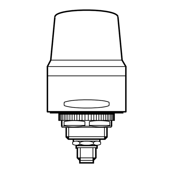
P_MZ_e200_0102
Table of
Contents
Previous
Page
Next
Page
1
2
3
4
5
Advertisement
Table of Contents
Need help?
Do you have a question about the DV2120 and is the answer not in the manual?
Ask a question
Questions and answers
Related Manuals for IFM DV2120
Outdoor Light IFM DV15 Series Operating Instructions Manual
5-segment signal lamp (22 pages)
Outdoor Light IFM DV2121 Operating Instructions Manual
1-segment signal lamp (16 pages)
Outdoor Light IFM DV2130 Operating Instructions Manual
1-segment signal lamp (16 pages)
Outdoor Light IFM DV2131 Operating Instructions Manual
1-segment signal lamp (16 pages)
Outdoor Light IFM KTE Series Operating Instructions Manual
Touch sensor lamp (23 pages)
Outdoor Light IFM O2D93 Series Operating Instructions Manual
Led dome light (13 pages)
This manual is also suitable for:
Dv2121
Dv2130
Dv2131
Table of Contents
Print
Rename the bookmark
Delete bookmark?
Delete from my manuals?
Login
Sign In
OR
Sign in with Facebook
Sign in with Google
Upload manual
Upload from disk
Upload from URL


Need help?
Do you have a question about the DV2120 and is the answer not in the manual?
Questions and answers