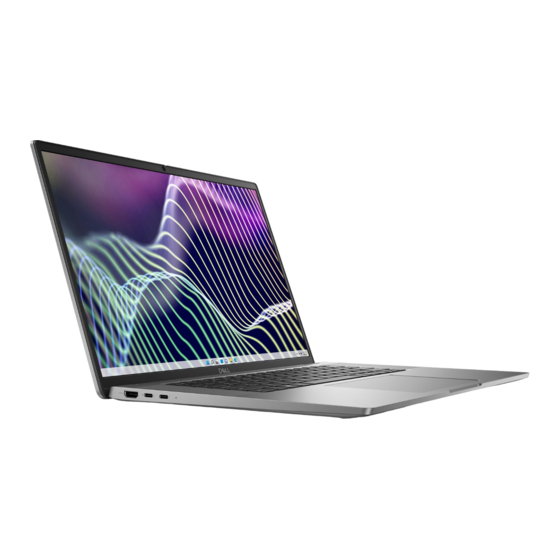
Dell Latitude 7640 Service Manual
Hide thumbs
Also See for Latitude 7640:
- User manual ,
- Technical manualbook (42 pages) ,
- Setup and specifications (29 pages)

Related Manuals for Dell Latitude 7640


Summary of Contents for Dell Latitude 7640
- Page 1 Latitude 7640 Service Manual Regulatory Model: P126F Regulatory Type: P126F001 March 2023 Rev. A00...
- Page 2 A WARNING indicates a potential for property damage, personal injury, or death. © 2023 Dell Inc. or its subsidiaries. All rights reserved. Dell Technologies, Dell, and other trademarks are trademarks of Dell Inc. or its subsidiaries. Other trademarks may be trademarks of their respective owners.
-
Page 3: Table Of Contents
After working inside your computer..........................9 BitLocker..................................9 Chapter 2: Removing and installing components................10 Recommended tools................................10 Screw list..................................... 10 Major components of Latitude 7640..........................11 NanoSIM-card tray................................13 Removing the nanoSIM-card tray ...........................13 Installing the nanoSIM-card tray ..........................14 Base cover................................... 15 Removing the base cover ............................ - Page 4 Deleting or changing an existing system setup password.................85 Clearing CMOS settings..............................85 Clearing BIOS (System Setup) and System passwords..................86 Clearing chassis intrusion alert ............................. 86 Chapter 5: Troubleshooting......................88 Handling swollen Lithium-ion batteries........................88 Dell SupportAssist Pre-boot System Performance Check diagnostics..............88 Contents...
- Page 5 LCD Built-in Self Test (BIST)........................... 90 System-diagnostic lights..............................90 Recovering the operating system..........................92 Real-Time Clock (RTC Reset)............................92 Backup media and recovery options..........................93 Wi-Fi power cycle................................93 Drain residual flea power (perform hard reset)......................93 Chapter 6: Getting help and contacting Dell................94 Contents...
-
Page 6: Chapter 1: Working Inside Your Computer
You should only perform troubleshooting and repairs as authorized or directed by the Dell technical assistance team. Damage due to servicing that is not authorized by Dell is not covered by your warranty. See the safety instructions that is shipped with the product or at www.dell.com/regulatory_compliance. -
Page 7: Safety Precautions
Ensure that your computer is shut down and the AC adapter is disconnected. a. Hold <B> key on the keyboard and press the power button for 3 seconds or until the Dell logo appears on the screen. b. Press any key to continue. -
Page 8: Esd Field Service Kit
Due to the increased density of semiconductors used in recent Dell products, the sensitivity to static damage is now higher than in previous Dell products. For this reason, some previously approved methods of handling parts are no longer applicable. Two recognized types of ESD damage are catastrophic and intermittent failures. -
Page 9: Transporting Sensitive Components
Transporting sensitive components When transporting ESD sensitive components such as replacement parts or parts to be returned to Dell, it is critical to place these parts in anti-static bags for safe transport. -
Page 10: Chapter 2: Removing And Installing Components
Removing and installing components NOTE: The images in this document may differ from your computer depending on the configuration you ordered. Recommended tools The procedures in this document may require the following tools: ● Phillips screwdriver #0 ● Phillips screwdriver #1 ●... -
Page 11: Major Components Of Latitude 7640
SIM-card tray bracket M2x2 Camera-cable bracket M2x2.5 Smart-card reader M2x2 System board M2x4 M2x2.5 I/O daughter-board M.2x2.5 Power button M1.6x1.7 Keyboard M1.6x1.7 Major components of Latitude 7640 The following image shows the major components of Latitude 7640. Removing and installing components... - Page 12 1. Base cover 2. Battery 3. System Board 4. Smartcard reader 5. Keyboard bracket 6. Keyboard 7. Speaker 8. Palm-rest and keyboard assembly Removing and installing components...
-
Page 13: Nanosim-Card Tray
18. WWAN crad shield 19. Coincell NOTE: Dell provides a list of components and their part numbers for the original system configuration purchased. These parts are available according to warranty coverages purchased by the customer. Contact your Dell sales representative for purchase options. -
Page 14: Installing The Nanosim-Card Tray
Steps 1. Insert a pin into the release hole of the nanoSIM-card tray and push inward until the tray is released. 2. Slide the nanoSIM-card tray out of the slot on the computer. 3. Remove the SIM card from the nanoSIM-card tray. 4. -
Page 15: Base Cover
Steps 1. Insert a pin into the hole of the nanoSIM-card tray and push inward until the tray is released. 2. Slide the nanoSIM-card tray out of the slot on the computer. 3. Place the SIM card into the nanoSIM-card tray with the metallic contact facing up. 4. - Page 16 Removing and installing components...
-
Page 17: Installing The Base Cover
Steps 1. Loosen the eight captive screws that secure the base cover to the palm-rest and keyboard assembly. 2. Using a plastic scribe, pry open the base cover starting from the recesses, which are located in the U-shaped indents at the top edge of the base cover, near the hinges. - Page 18 Removing and installing components...
-
Page 19: Solid-State Drive
Steps 1. Place the base cover on top of the palm-rest and keyboard assembly. 2. Align the screw holes on the base cover with the screw holes on the palm-rest and keyboard assembly, and snap the base cover latches into place. 3. -
Page 20: Installing The M.2 2230 Solid-State Drive
2. Remove the base cover. About this task NOTE: The M.2 card that is installed on your computer depends on the configuration ordered. Supported card configurations on the M.2 card slot are: ● M.2 2230 solid-state drive The following image indicates the location of the M.2 2230 solid-state drive and provides a visual representation of the removal procedure. -
Page 21: Wireless Wide Area Network (Wwan) Card
3. Verify if the storage device is installed correctly: a. Turn on or restart your system. b. Press F2 when the Dell logo is displayed on the screen to enter the system setup (BIOS) program. NOTE: A list of storage devices are displayed under the System Information in the General group. -
Page 22: Installing The 4G Wwan Card
About this task NOTE: This procedure applies only to computers shipped with a 4G WWAN card installed. NOTE: When reinstalling the WWAN card shielding cover, ensure that the shielding cover is inserted into the clips on the I/O daughter-board. The following images indicate the location of the 4G WWAN card and provide a visual representation of the removal procedure. Steps 1. -
Page 23: Removing The 5G Wwan Card
Steps 1. Align the notch on the 4G WWAN card with the tab on the M.2-card slot on the system board. 2. Slide the 4G WWAN card firmly into the M.2-card slot on the system board. 3. Connect the antenna cables to the connectors on the 4G WWAN card. 4. -
Page 24: Installing The 5G Wwan Card
Steps 1. Pry the WWAN shielding cover from the top-left side of the shielding cover and remove it from the computer. 2. Lift the 5G WWAN-card bracket off the system board. 3. Remove the single screw (M2x2.5) that secures the 5G WWAN-card bracket to the system board. 4. - Page 25 Steps 1. Align the notch on the 5G WWAN card with the tab on the M.2-card slot on the system board. 2. Slide the 5G WWAN card firmly into the M.2-card slot on the system board. 3. Connect the antenna cables to the connectors on the 5G WWAN card. 4.
-
Page 26: Battery
● If the battery gets stuck inside your computer as a result of swelling, do not try to release it as puncturing, bending, or crushing a lithium-ion battery can be dangerous. In such an instance, contact Dell technical support for assistance. See www.dell.com/contactdell. -
Page 27: Installing The 2-Cell Battery
Steps 1. Use the pull tab to disconnect the battery cable from the connector on the system board. 2. Loosen the five captive screws that secures the 2-cell battery to the palm-rest and keyboard assembly. 3. Lift the 2-cell battery along with the battery cable off the palm-rest and keyboard assembly. 4. -
Page 28: Removing The 3-Cell Battery
Steps 1. Carefully push the battery filler upwards to attach it to the 2-cell battery. 2. Place the 2-cell battery along with the battery cable on the palm-rest and keyboard assembly. 3. Align the screw holes on the 2-cell battery to the screw holes on the palm-rest and keyboard assembly. 4. -
Page 29: Installing The 3-Cell Battery
About this task The following image indicates the location of the 3-cell battery and provides a visual representation of the removal procedure. Steps 1. Disconnect the battery cable from the connector on the system board, if it was not disconnected earlier. 2. -
Page 30: Battery Cable
Steps 1. Place the 3-cell battery along with the battery cable on the palm-rest and keyboard assembly. 2. Adhere the tape to secure the battery cable to the battery. 3. Align the screw holes on the 3-cell battery to the screw holes on the palm-rest and keyboard assembly. 4. -
Page 31: Installing The Battery Cable
Steps 1. Flip the battery and unroute the battery cable from the routing guides on the battery. 2. Disconnect the battery cable from the connector on the battery. 3. Lift the battery cable away from the battery. NOTE: Dummy filler for a 2-cell battery is not required for lightweight WLAN configuration. Installing the battery cable Prerequisites If you are replacing a component, remove the existing component before performing the installation procedure. -
Page 32: Heat Sink
Steps 1. Connect the battery cable to the connector on the battery. 2. Route the battery cable through the routing guides on the battery. Next steps 1. Install the 2-cell battery the3-cell battery, whichever is applicable. 2. Install the base cover. -
Page 33: Installing The Heat-Sink And Fan Assembly
About this task NOTE: The heat-sink may become hot during normal operation. Allow sufficient time for the heat-sink to cool before you touch it. NOTE: For maximum cooling of the processor, do not touch the heat transfer areas on the heat-sink. The oils in your skin can reduce the heat transfer capability of the thermal grease. -
Page 34: Coin-Cell Battery
Steps 1. Place the heat-sink on the system board. 2. Align the screw holes on the heat-sink and fan assembly with the screw holes on the system board. 3. Replace the four screws (M2x4) that secure the system fan to the system board. 4. -
Page 35: Installing The Coin-Cell Battery
Steps 1. Remove the shielding cover that holds the coin-cell battery. 2. Disconnect the coin-cell battery cable from the connector on the system board. 3. Unroute the coin-cell battery cable from the routing guides on the system board. 4. Using a plastic scribe, pry the coin-cell battery off its slot on the system board. Installing the coin-cell battery Prerequisites If you are replacing a component, remove the existing component before performing the installation procedure. -
Page 36: Display Assembly
Steps 1. Place the coin-cell battery into its slot on the system board. 2. Route the coin-cell battery cable back to the routing guides on the system board. 3. Connect the coin-cell battery cable to the connector on the system board. 4. - Page 37 Removing and installing components...
- Page 38 Steps NOTE: The steps from 1 to 4 apply only to computers shipped with a WWAN antenna installed in the display assembly. Remove the single screw (M2x2) securing the Darwin antenna cable bracket on the system board. 2. Remove the Darwin antenna cable bracket from the system board. 3.
-
Page 39: Installing The Display Assembly
NOTE: The display assembly is a Hinge-Up Design (HUD) assembly and cannot be further disassembled once it is removed from the bottom chassis. If any components in the display assembly are malfunctioning and is required to be replaced, replace the entire display assembly. Figure 1. - Page 40 Removing and installing components...
- Page 41 Steps 1. Place the display assembly on a flat surface. 2. Slide the base assembly at an angle and gently press down on hinges to align the screw holes on the display hinges with screw holes on the system board. 3.
-
Page 42: Speakers
NOTE: This procedure applies only to computers shipped with a WWAN card installed. 2. Install the base cover. 3. Follow the procedure in After working inside your computer. Speakers Removing the speakers Prerequisites 1. Follow the procedure in Before working inside your computer. -
Page 43: Installing The Speakers
4. Lift the speakers, along with the cable, off the palm-rest and keyboard assembly. Installing the speakers Prerequisites If you are replacing a component, remove the existing component before performing the installation procedure. About this task NOTE: If the rubber grommets are pushed out when removing the speakers, push them back in before replacing the speakers. -
Page 44: Smart Card Reader
2. Follow the procedure in Before working inside your computer. Smart card reader Removing the smart card reader Prerequisites 1. Follow the procedure in Before working inside your computer. 2. Remove the base cover. 3. Remove the speakers. 4. Remove the 2-cell battery the3-cell battery, whichever is applicable. - Page 45 Removing and installing components...
-
Page 46: Installing The Smart Card Reader
Steps 1. Open the latch and disconnect the clickpad flexible flat cable, keyboard backlight flexible printed circuit, and keyboard flexible printed circuit from the connector on the clickpad. 2. Disconnect the smart card reader flexible flat cable from the respective connectors on the clickpad. 3. - Page 47 Removing and installing components...
- Page 48 Steps 1. Align and place the smart card reader on the palm-rest and keyboard assembly. 2. Replace the four screws (M2x2) that secure the smart card reader to the palm-rest and keyboard assembly. 3. Adhere the smart card reader cable on the palm-rest and keyboard assembly. 4.
-
Page 49: System Board
System board Removing the system board Prerequisites 1. Follow the procedure in Before working inside your computer. 2. Remove the base cover. 3. Remove the M.2 2230 solid-state drive. 4. Remove the 2-cell battery the3-cell battery, whichever is applicable. 5. Remove the heat-sink. About this task The following image indicates the connectors on your system board. - Page 50 Steps 1. Remove the single screw (M2x2) screw securing the WLAN module bracket in place. 2. Remove the WLAN module bracket from the system. 3. Disconnect the WLAN Main and Aux antenna from the WLAN module. 4. Remove the two screws (M2x2) securing the display cable bracket on the system board. 5.
-
Page 51: Installing The System Board
10. Remove the system board from the system. NOTE: For Latitude 7640 laptop models with a 5G WWAN card, if replacing the system board, peel off the CPU absorber sticker and transfer it over to the new system board. 11. Carefully lift and remove the system board away from the palm-rest and keyboard assembly. - Page 52 1. LCD connector 2. Touchscreen and IR-camera cable connector 3. M.2 solid-state drive connector 4. Clickpad FFC connector 5. Battery cable connector 6. USH daughter-board FFC connector 7. Coin-cell battery cable connector 8. Fan connector NOTE: For computers shipped without a WWAN card, a WWAN shielding cover and WWAN bracket is pre-installed to the computer.
- Page 53 Steps 1. Place the system board into the respective slot on the palm-rest and keyboard assembly. NOTE: Transfer the reusable WLAN absorbers to the new system board while replacing the system board. 2. Replace the three screws (M2x2.5) securing the system board in place. 3.
-
Page 54: Wlan-Antenna Module
WLAN-antenna module Removing the WLAN-antenna module Prerequisites 1. Follow the procedure in Before working inside your computer. 2. Remove the base cover. 3. Remove the SSD. 4. Remove the WWAN card. 5. Remove the 2-cell battery the3-cell battery, whichever is applicable. 6. -
Page 55: Installing The Wlan-Antenna Module
Steps 1. For computers shipped with WWAN antennas, remove the single screw (M2x2) that secure the Darwin antenna cable bracket to the system board. 2. Remove the Darwin antenna cable bracket from the system board. 3. Unroute the two darwin antenna cables, and green P-sensor cable from the routing guide on the I/O daughter-board. 4. -
Page 56: I/O Daughter-Board
Steps 1. Slide and replace the WLAN-antenna module to the WLAN-antenna module slot on the system board. 2. Route the WLAN-antenna cables from the routing guides on the system board. 3. Replace the four screws (M1.6x2.5) that secure the WLAN-antenna module bracket on the system board. 4. - Page 57 About this task CAUTION: Remove the system board before removing the I/O daughter-board as a part of the I/O daughter- board is underneath the system board. CAUTION: Do not try to remove the I/O daughter-board along with the system board. The following image indicates the location of the I/O daughter-board and provides a visual representation of the removal procedure.
- Page 58 Steps 1. Remove the single screw (M2x2) screw that secures the 4G WWAN card extension bracket to palm-rest and keyboard assembly for the models shipped with a 4G WWAN card. 2. Remove the 4G WWAN card bracket from the system for the models shipped with a 4G WWAN card. 3.
-
Page 59: Installing The I/O Daughter-Board
17. Lift and remove the I/O daughter-board from the palm-rest and keyboard assembly. NOTE: The thermal pad sticker adhered onto the WWAN card compartment must be peeled off and transferred over to the replacement I/O daughter-board. For 4G configuration For 5G configuration Installing the I/O daughter-board Prerequisites If you are replacing a component, remove the existing component before performing the installation procedure. - Page 60 NOTE: When replacing an I/O daughter-board for models shipped with a 5G WWAN card, the thermal pad sticker adhered onto the WWAN card compartment must be peeled off and transferred over to the replacement I/O daughter-board. About this task The following image indicates the location of the I/O daughter-board and provides a visual representation of the installation procedure.
- Page 61 Steps 1. Adhere the WWAN thermal pad affixed to the WWAN card compartment and move it to the new I/O daughter-board if you're replacing the I/O daughter-board for models shipped with 5G WWAN card. 2. Place the I/O daughter-board in its compartment from the gap in its top side and place it on the computer. 3.
-
Page 62: Power Button With Optional Fingerprint Reader
Next steps 1. Install the WWAN card. NOTE: This procedure applies only to computers shipped with a WWAN card installed. 2. Install the base cover. 3. Follow the procedure in After working inside your computer. Power button with optional fingerprint reader Removing the power button with optional fingerprint reader Prerequisites 1. -
Page 63: Installing The Power Button With Optional Fingerprint Reader
NOTE: This step applies only to computers shipped with a power button with fingerprint reader installed. 3. Lift the power button off the slot on the palm-rest and keyboard assembly. Installing the power button with optional fingerprint reader Prerequisites If you are replacing a component, remove the existing component before performing the installation procedure. About this task The following images indicate the location of the power button with optional fingerprint reader and provide a visual representation of the installation procedure. -
Page 64: Keyboard
Keyboard Removing the keyboard Prerequisites 1. Follow the procedure in Before working inside your computer. 2. Remove the base cover. 3. Remove the solid-state drive. 4. Remove the WWAN card. NOTE: This procedure applies only to computers shipped with a WWAN card installed. 5. -
Page 65: Installing The Keyboard
Steps 1. Peel the USH daughter-board flexible flat cable from the back of the keyboard. NOTE: This step applies only to computers shipped with a USH daughter-board installed. 2. Open the latch and disconnect the keyboard and keyboard backlight flat cable from the connector on the clickpad. 3. - Page 66 Steps 1. Align the screw holes on the keyboard to the screw holes on the keyboard support plate and place the keyboard on the keyboard support plate. 2. Align and place the keyboard assembly in to its slot in the computer. 3.
-
Page 67: Palm-Rest Assembly
NOTE: This step applies only to computers shipped with a USH daughter-board installed. Next steps 1. Follow the procedure in Before working inside your computer. 2. Install the system board. 3. Install the Power button. 4. Install the daughter-board. 5. Install the speakers. 6. -
Page 68: Installing The Palm-Rest Assembly
Steps 1. For computers shipped with a carbon fiber palm-rest, use a fine-tipped instrument to push the nanoSIM outwards to remove it from its slot on the palm-rest assembly. 2. After performing the pre-requisites, you are left with the palm-rest assembly. Installing the palm-rest assembly Prerequisites If you are replacing a component, remove the existing component before performing the installation procedure. - Page 69 Steps 1. For computers shipped with a carbon fiber palm-rest, align to the slot on the palm-rest assembly. 2. Place the palm-rest assembly on a flat surface and perform the post-requisites to install the palm-rest assembly. Next steps 1. Install the keyboard. 2.
-
Page 70: Chapter 3: Drivers And Downloads
Drivers and downloads When troubleshooting, downloading or installing drivers it is recommended that you read the Dell Knowledge Base article, Drivers and Downloads FAQ 000123347. Drivers and downloads... -
Page 71: Chapter 4: Bios Setup
BIOS setup CAUTION: Unless you are an expert computer user, do not change the settings in the BIOS Setup program. Certain changes can make your computer work incorrectly. NOTE: Depending on the computer and its installed devices, the items listed in this section may or may not be displayed. NOTE: Before you change BIOS Setup program, it is recommended that you write down the BIOS Setup program screen information for future reference. -
Page 72: System Setup Options
Depending on your system and its installed devices, the items that are listed in this section may or may not appear. Table 3. System setup options—System information menu Overview Latitude 7640 BIOS Version Displays the BIOS version number. Service Tag Displays the Service Tag of the system. - Page 73 Table 3. System setup options—System information menu (continued) Overview 64-Bit Technology Displays whether 64-bit technology is used. Memory Information Memory Installed Displays the total system memory installed. Memory Available Displays the total system memory available. Memory Speed Displays the memory speed. Memory Channel Mode Displays single or dual channel mode.
- Page 74 By default, the Video/Power only on Type-C Ports option is disabled. Type-C Dock Override Enables to use connected Type-C Dell Dock to provide data stream with external USB ports disabled. When Type-C Dock override is enabled, the Video/Audio/Lan submenu is activated.
- Page 75 Table 6. System setup options—Storage menu Storage SATA/NVMe Operation SATA/NVMe Operation Set the operating mode of the integrated storage device controller. By default, the RAID On option is enabled. Storage Interface Port Enablement This page allows you to enable the onboard drives. By default, the M.2 PCIe SSD option is enabled.
- Page 76 By default, the Optimized option is enabled. USB Wake Support Wake on Dell USB-C Dock When enabled, connecting a Dell USB-C Dock will wake the system from Standby, Hibernate, and Power Off. By default, the Wake on Dell USB-C Dock option is enabled.
- Page 77 Table 9. System setup options—Power menu (continued) Power Enabled Lid Switch Enable or disable the lid switch. By default, the Enable Lid Switch option is enabled. Power On Lid Open When enabled, allows the system to power up from the off state whenever the lid is opened.
- Page 78 Table 10. System setup options—Security menu (continued) Security By default, the option is enabled. WARNING: The 'Permanently Disabled' option can only be selected once. When 'Permanently Disabled' is selected, Absolute Persistence cannot be re-enabled. No further changes to the Enable/Disable states are allowed. NOTE: The Enable/Disable options will be unavailable while Computrace is in the activated state.
- Page 79 By default, the option is enabled. Dell Auto OS Recovery Threshold Controls the automatic boot flow for SupportAssist System Resolution Console and for Dell operating system Recovery Tool. By default, the threshold value is set to 2. Table 13. System setup options—System Management menu...
- Page 80 Table 13. System setup options—System Management menu (continued) System Management By default, the option is disabled. Auto on Time Enable to set the system to turn on automatically every day or on a preselected date and time. This option can be configured only if the Auto On Time is set to Everyday, Weekdays, or Selected Days.
- Page 81 Table 15. System setup options—Pre-boot Behavior menu (continued) Pre-boot Behavior MAC Address Pass-Through Replaces the external NIC MAC address with the selected MAC address from the system. By default, the System Unique MAC Address option is enabled. Sign of Life Early Keyboard Backlight By default, the Early Keyboard Backlight option is enabled.
-
Page 82: Updating The Bios
For more information on this subject, search in the Knowledge Base Resource at www.dell.com/support. Steps 1. Go to www.dell.com/support. 2. Click Product support. In the Search support box, enter the Service Tag of your computer, and then click Search. BIOS setup... -
Page 83: Updating The Bios In Linux And Ubuntu
Updating the BIOS in Windows to download the latest BIOS setup program file. 2. Create a bootable USB drive. For more information, search in the Knowledge Base Resource at www.dell.com/support. 3. Copy the BIOS setup program file to the bootable USB drive. -
Page 84: System And Setup Password
Most of the Dell computers built after 2012 have this capability, and you can confirm by booting your computer to the F12 One-Time Boot Menu to see if BIOS FLASH UPDATE is listed as a boot option for your computer. If the option is listed, then the BIOS supports this BIOS update option. -
Page 85: Deleting Or Changing An Existing System Setup Password
Steps 1. In the System BIOS or System Setup screen, select Security and press Enter. The Security screen is displayed. 2. Select System/Admin Password and create a password in the Enter the new password field. Use the following guidelines to assign the system password: ●... -
Page 86: Clearing Bios (System Setup) And System Passwords
Clearing BIOS (System Setup) and System passwords About this task To clear the system or BIOS passwords, contact Dell technical support as described at www.dell.com/contactdell. NOTE: For information on how to reset Windows or application passwords, refer to the documentation accompanying Windows or your application. - Page 87 To clear the alert, set the Clear Intrusion Warning to ON in the Security menu of the BIOS setup. BIOS setup...
-
Page 88: Chapter 5: Troubleshooting
● Using a non-Dell or incompatible battery may increase the risk of fire or explosion. Replace the battery only with a compatible battery purchased from Dell that is designed to work with your Dell computer. Do not use a battery from other computers with your computer. -
Page 89: Running The Supportassist Pre-Boot System Performance Check
Running the SupportAssist Pre-Boot System Performance Check Steps 1. Turn on your computer. 2. As the computer boots, press the F12 key as the Dell logo appears. 3. On the boot menu screen, select the Diagnostics option. 4. Click the arrow at the bottom left corner. -
Page 90: Lcd Power Rail Test (L-Bist)
LCD Built-in Self Test (BIST) Dell laptops have a built-in diagnostic tool that helps you determine if the screen abnormality you are experiencing is an inherent problem with the LCD (screen) of the Dell laptop or with the video card (GPU) and PC settings. - Page 91 (AC, battery, coin cell) and errors drain flea power by pressing and holding down power button for 3-5 seconds. CPU failure ● Run the Dell Support Assist/Dell Diagnostics tool. ● If problem persists, replace the system board. System board failure (included ●...
-
Page 92: Recovering The Operating System
It enables you to diagnose hardware issues, repair your computer, back up your files, or restore your computer to its factory state. You can also download it from the Dell Support website to troubleshoot and fix your computer when it fails to boot into their primary operating system due to software or hardware failures. -
Page 93: Backup Media And Recovery Options
Backup media and recovery options It is recommended to create a recovery drive to troubleshoot and fix problems that may occur with Windows. Dell proposes multiple options for recovering Windows operating system on your Dell PC. For more information. see... -
Page 94: Chapter 6: Getting Help And Contacting Dell
Getting help and contacting Dell Self-help resources You can get information and help on Dell products and services using these self-help resources: Table 22. Self-help resources Self-help resources Resource location Information about Dell products and services www.dell.com Tips Contact Support In Windows search, type Contact Support, and press Enter.
Need help?
Do you have a question about the Latitude 7640 and is the answer not in the manual?
Questions and answers