Table of Contents
Advertisement
Operator's Manual
208cc Engine
Rear Tine Tiller
Electric Start
Model No. C459-62206-1
CAUTION: Before using this
product, read this manual
and follow all safety rules
and operating instructions.
Sears Canada Inc., 290 Yonge Street, Toronto, On M5B 2C3
®
Visit our web: sears.ca
• SAFETY
• ASSEMBLY
• OPERATION
• MAINTENANCE
• PARTS LIST
769-07880A
12/11/13
Advertisement
Table of Contents

Related Manuals for Craftsman C459-62206-1


Summary of Contents for Craftsman C459-62206-1
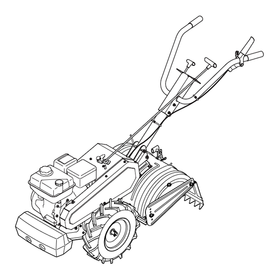
- Page 1 Operator’s Manual ® 208cc Engine Rear Tine Tiller Electric Start Model No. C459-62206-1 • SAFETY • ASSEMBLY • OPERATION • MAINTENANCE • PARTS LIST CAUTION: Before using this product, read this manual and follow all safety rules and operating instructions.
-
Page 2: Table Of Contents
TABLE OF CONTENTS Safe Operation Practices ..... 3 Parts List (Tiller) ......26 Safety Symbols . -
Page 3: Safe Operation Practices
SAFETY INSTRUCTIONS WARNING DANGER This machine was built to be operated according to the safe opera- This symbol points out important safety instructions which, if not tion practices in this manual. As with any type of power equipment, followed, could endanger the personal safety and/or property of carelessness or error on the part of the operator can result in yourself and others. - Page 4 SAFETY INSTRUCTIONS Safe Handling of Gasoline: • Look down and behind and use care when in reverse or pulling machine towards you. To avoid personal injury or property damage use extreme care in handling gasoline. Gasoline is extremely flammable and the vapors are •...
- Page 5 SAFETY INSTRUCTIONS NOTICE REGARDING EMISSIONS • Do not change the engine governor settings or over-speed the engine. The governor controls the maximum safe operating speed Engines which are certified to comply with California and federal of engine. EPA emission regulations for SORE (Small Off Road Equipment) are •...
-
Page 6: Safety Symbols
SAFETY INSTRUCTIONS SAFETY SYMBOLS This page depicts and describes safety symbols that may appear on this product. Read, understand, and follow all instructions on the machine before attempting to assemble and operate. Symbol Description READ THE OPERATOR’S MANUAL(S) Read, understand, and follow all instructions in the manual(s) before attempting to assemble and operate WARNING—... -
Page 7: Labels
LABELS Craftsman Tiller Model No. C459-62206... -
Page 8: Assembly & Adjustments
ASSEMBLY NOTE: This unit is shipped without gasoline or oil in the engine. Be Raise the tine shield hinge flap assembly and insert the depth certain to service engine with gasoline and oil as instructed in the stake assembly in the slot, under the tine shield and up through Operation section of this manual before operating your machine. - Page 9 ASSEMBLY Swing Handle Link Handle Cotter Pin Handle Assembly Adjustment Crank Retainer Bracket Top Hex Screw T-Knob Handle Bracket Assembly Flange Lock Nuts Figure 3 Figure 5 Side View Flat Washer Rubber Washer Cotter Pin T-Knob Lock Washer Adjustable Fitting Figure 6 Figure 4 ATTACHING THE CLUTCH CABLE...
- Page 10 ASSEMBLY SET-UP Insert the cable barrel into the cable barrel holder, insert the barrel and barrel holder into the clutch handle and secure with the Tire Pressure hex screw. See Figure 7. Check the air pressure in both tires. The air pressure should be between 15-20 PSI.
- Page 11 ASSEMBLY ADJUSTMENTS Fuel Recommendations Use automotive gasoline (unleaded or low leaded to minimize combus- Clutch Cable tion chamber deposits) with a minimum of 87 octane. Gasoline with Check the adjustment of the clutch cable as follows: up to 10% ethanol or 15% MTBE (Methyl Tertiary Butyl Ether) can be Position the tiller so the front counterweight is against a solid used.
-
Page 12: Operation
120V power source. STOP position. Meets ANSI Safety Standards Craftsman Tillers conform to the safety standard of the American National Standards Institute (ANSI). - Page 13 OPERATION OIL FILL CAP & DIPSTICK HANDLE ADJUSTMENT LOCK The handle may be adjusted to the height desired by unlocking the Engine oil level can be checked and oil added through the oil fill. Handle Adjustment Lock, then moving the handle bars to the desired NOTE: This unit was shipped WITHOUT oil in the engine.
- Page 14 OPERATION TO STOP ENGINE Push the choke lever to the CHOKE position. If the engine is warm, place the choke in the RUN position instead of CHOKE To stop the wheels and tines, release the Clutch Lever. . See Figure 14. Move throttle control lever to slow (turtle) position.
- Page 15 OPERATION TILLING TIPS & TECHNIQUES • When breaking up sod and for shallow cultivation, use the setting which gives 1” of tilling depth (second hole from the top). Place WARNING the side shields in their lowest position. • For further depth, raise the depth stake and side shields and also Before tilling, contact your telephone or utilities company and inquire make one or two more passes over the area.
- Page 16 OPERATION Suggested Tilling Patterns • If the garden size will not permit lengthwise and then crosswise tilling, then overlap the first passes by one-half a tiller width, fol- • When preparing a seedbed, go over the same path twice in the lowed by successive passes at one-quarter width.
- Page 17 OPERATION Terrace Gardening • The ramps must be strong enough to support the combined weight of the tiller and any handlers. The ramps should provide To create a terrace, start at the top of the slope and work down good traction to prevent slipping; they should also have side rails Go back and forth across the first row.
-
Page 18: Service & Maintenance
SERVICE AND MAINTENANCE MAINTENANCE SCHEDULE WARNING Follow the maintenance schedule given below. This chart describes Before performing any type of maintenance/service, disengage all service guidelines only. Use the Service Log column to keep track of controls and stop the engine. Wait until all moving parts have come to completed maintenance tasks. - Page 19 SERVICE AND MAINTENANCE Servicing the Air Cleaner Remove the spark plug boot and use a spark plug wrench to remove the plug. See Figure 22. WARNING Never use gasoline or low flash point solvents for cleaning the air cleaner element. A fire or explosion could result. The air cleaner prevents damaging dirt, dust, etc., from entering the carburetor and being forced into the engine and is important to engine Spark Plug...
- Page 20 SERVICE AND MAINTENANCE Check Engine Oil With engine OFF but still warm, disconnect spark plug wire and keep it away from spark plug. Check oil before each use. Stop engine and wait several minutes Remove oil drain cap located at the end of the oil drain pipe , and before checking oil level.
- Page 21 SERVICE AND MAINTENANCE LUBRICATION BELT REPLACEMENT After every 10 operating hours, oil or grease the lubrication points. Use Your tiller has been engineered with a belt designed for long life and clean lubricating oil (#30 weight motor oil is suitable) and clean general optimal performance.
- Page 22 SERVICE AND MAINTENANCE ADJUSTMENTS Remove the idler pulley by removing the hex screw and jam lock nut. See Figure 28. Handle Remove the old belt and install the new belt. Follow the instruc- The handle may be adjusted to the desired height. Refer to the tions in reverse order to re-install the belt keeper and belt cover.
- Page 23 SERVICE AND MAINTENANCE Idler Pulley Rod After the belt tension has been adjusted, if the belt is excessively stretched, you may need to adjust the idler pulley rod. This can be checked easily. With the engine off and the clutch control bail disengaged, shift the gear selection handle to each forward mode.
-
Page 24: Off-Season Storage
OFF-SEASON STORAGE WARNING Never store tiller with fuel in tank indoors or in poorly ventilated areas where fuel fumes may reach an open flame, spark, or pilot light as on a furnace, water heater, clothes dryer, or gas appliance. PREPARING THE TILLER WARNING When the tiller won’t be used for an extended period, prepare it for Never leave engine unattended while it is running. -
Page 25: Troubleshooting
TROUBLESHOOTING WARNING Before performing any type of maintenance/service, disengage all controls and stop the engine. Wait until all moving parts have come to a complete stop. Disconnect spark plug wire and ground it against the engine to prevent unintended starting. Always wear safety glasses during operation or while performing any adjustments or repairs. Problem Cause Remedy... -
Page 26: Parts List (Tiller)
PARTS LIST Craftsman Tiller — Model No. C459-62206-1... - Page 27 PARTS LIST Craftsman Tiller — Model No. C459-62206-1 Ref. No. Part No. Description Ref. No. Part No. Description 710-3008 Hex Screw, 5/16-18 x .75 2725 Cable Tie 710-3056 Hex Screw, 5/16-18 x 3.25 649-04101-0691 Upper Handle Assembly 710-3130 Hex Screw, 3/8-16 x 3.25...
- Page 28 PARTS LIST Craftsman Tiller — Model No. C459-62206-1...
- Page 29 PARTS LIST Craftsman Tiller — Model No. C459-62206-1 Ref. No. Part No. Description Ref. No. Part No. Description 786-0064A Idler Pulley Bracket 686-0191B-0691 Belt Keeper Assembly Bracket 786-0187-0637 Shift Cover Bracket 686-04044A-0691 Belt Cover Assembly Bracket 786-0193-0637 Idler Belt Keeper 710-0170 Hex Lock Screw, 5/16-24 x .625...
- Page 30 PARTS LIST Craftsman Tiller — Model No. C459-62206-1 25 39...
- Page 31 PARTS LIST Craftsman Tiller — Model No. C459-62206-1 Ref. No. Part No. Description Ref. No. Part No. Description 921-0378 Shaft Seal, 1.0 611-0021 Tine Shaft Assembly 721-0379 Shaft Seal, .75 611-0128 Jack Shaft Assembly 786-0238 Positioner Gear Bracket 611-0129 Shift Input Shaft Assembly...
-
Page 32: Warranty Statement
WARRANTY STATEMENT General: Craftsman products are warranted to be free from defects in materials or workmanship for a specific time period as set-out below (the “Warranty Period”). Warranties extend to the original purchaser of a Craftsman product only. Purchases made through an online auction or through any website other than www.sears.ca are excluded. -
Page 33: Statement
(This page applicable in the U.S.A. and Canada only.) Sears Brands Management Corporation (Sears), the California Air Resources Board (CARB) and the United States Environmental Protection Agency (U.S. EPA) Emission Control System Warranty Statement (Owner’s Defect Warranty Rights and Obligations) EMISSION CONTROL WARRANTY COVERAGE IS APPLICABLE TO CERTI- YEAR 1997 AND LATER ENGINES WHICH ARE PURCHASED AND USED FIED ENGINES PURCHASED IN CALIFORNIA IN 1995 AND THEREAF-... -
Page 34: Emisions Durability Period
Look For Relevant Emissions Durability Period and Air Index Information On Your Engine Emissions Label Engines that are certified to meet the California Air Resources Board (CARB) Tier 2 Emission Standards must display information regarding the Emissions Durability Period and the Air Index. Sears Brands Management Corporation makes this information available to the consumer on our emission labels. -
Page 35: Repair Protection Agreement
REPAIR PROTECTION AGREEMENT Congratulations on making a smart purchase. Your new Craftsman® Once you purchase the Agreement, a simple phone call is all that it product is designed and manufactured for years of dependable opera- takes for you to schedule service. You can call anytime day or night, or tion. - Page 36 02488 Trademarks of Sears Brands Management Corp. used under license by Sears Canada Marque déposée / Marque de commerce de Sears Brands Management Corp. utilisée en vertu d’une licence de Sears Canada...
- Page 37 NOTES...
Need help?
Do you have a question about the C459-62206-1 and is the answer not in the manual?
Questions and answers