
Subscribe to Our Youtube Channel
Related Manuals for ADDAC System VINTAGE PRE ADDAC712


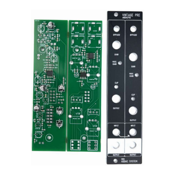
Summary of Contents for ADDAC System VINTAGE PRE ADDAC712
- Page 2 ADDAC712 Assembly Guide February.2023 ADDAC SYSTEM page 2...
- Page 3 Then solder the other pad. STEP 3: Next place and solder all transistors, then trim the excess legs with a cutting pliers. ADDAC SYSTEM page 3...
- Page 4 Notice the capacitors orientation, place their legs through the pcb holes and solder them to the pcb. STEP 6: Place and solder the remaining 470uf capacitors. Notice the part polarity orientation. STEP 7: Place and solder the 2x5 boxed pinheader. Notice the indent orientation. ADDAC SYSTEM page 4...
- Page 5 ADDAC712 Assembly Guide STEP 8: Place and solder the 2x4 pinheader. STEP 9: Attach the spacers to the front pcb as shown below, notice the white plastic screw location. ADDAC SYSTEM page 5...
- Page 6 ADDAC712 Assembly Guide STEP 10: Align both pcbs toghether and solder the pinheader to the top pcb. STEP 11: Next locate the jacks and cut the thinest leg like shown below. ADDAC SYSTEM page 6...
- Page 7 Place the remaining parts on the pcb, allign the front panel and tighten the jacks and pots’ nuts. Non-threaded Jacks Threaded Jacks Non-threaded Jacks Threaded Jacks STEP 13: Adjust the height of the pcb keeping it parallel to the front panel and proceed to solder all parts. Keep lines parallel ADDAC SYSTEM page 7...
- Page 8 ADDAC712 Assembly Guide Finish it by placing the knobs and you’ve finished the assembly process! You’re all done! Happy patching! ADDAC SYSTEM page 7...
-
Page 9: Assembly Guide
For feedback, comments or problems please contact us at: addac@addacsystem.com ADDAC712 ASSEMBLY GUIDE Revision.01 February.2023... - Page 10 ADDAC712 Assembly Guide STEP 14: Next attach the bottom pcb and tighten the two bottom screws. ADDAC SYSTEM page 8...
Need help?
Do you have a question about the VINTAGE PRE ADDAC712 and is the answer not in the manual?
Questions and answers