
Subscribe to Our Youtube Channel
Related Manuals for ADDAC System ADDAC710


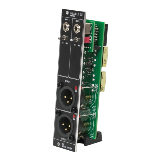
Summary of Contents for ADDAC System ADDAC710
- Page 2 ADDAC710 Assembly Guide February.2023 ADDAC SYSTEM page 2...
- Page 3 ADDAC710 Assembly Guide STEP 1: Grab the pcb, gently brake it apart and trim the excess with a cutting plier. STEP 2: Place and solder the 2x5 boxed pinheader. Notice the indent orientation. ADDAC SYSTEM page 3...
- Page 4 ADDAC710 Assembly Guide STEP 3: Place and solder the 1X5 pinheader. STEP 4: Allign both pcbs and solder the pinheader to the top pcb ADDAC SYSTEM page 4...
- Page 5 ADDAC710 Assembly Guide STEP 5: Place and solder the transformers, notice there’s one leg which is placed at an odd spacing which defines the orientation of the part. ADDAC SYSTEM page 5...
- Page 6 ADDAC710 Assembly Guide STEP 6: Locate the jacks and cut the thinest leg like shown below. STEP 7: Place the remaing parts on the pcbs, allign the front panel and tighten the jack nuts. Proceed by soldering the front panel parts, then attach the bottom pcb.
- Page 7 ADDAC710 Assembly Guide Finish it by fixing the XLR connectors with the screws and soldering the connectors. You’re all done! Happy patching! ADDAC SYSTEM page 7...
-
Page 8: Assembly Guide
For feedback, comments or problems please contact us at: addac@addacsystem.com ADDAC710 ASSEMBLY GUIDE Revision.01 February.2023...
Need help?
Do you have a question about the ADDAC710 and is the answer not in the manual?
Questions and answers