Table of Contents
Advertisement
Quick Links
About this Practice:
This document has been reissued to:
•
Update Figs. 1-5.
Reissued Practices: Updated and
new content can be identified by a
banner in the right margin.
Issue date: May 1997
Copyright 1997 by Dantel, Inc. • Dantel is a registered trademark of Dantel, Inc. • ISO 9001 Registered
O
RDER
S
AND
PEAKER
Table of Contents
CAUTION
•
Install or remove modules from the shelf only when the power is off.
If you install a module in the shelf with the power on, the internal
circuitry may suffer damage and the product warranty will be void.
•
Remove and install circuit boards only in a static-safe environment
(use antistatic wrist straps, smocks, footwear, etc.).
•
Keep circuit boards in their antistatic bags when they are not in use.
•
Do not ship or store circuit boards near strong electrostatic, electromag-
netic, magnetic, or radioactive fields.
•
For more complete information on electrostatic discharge safety
precautions, refer to Bellcore
Printed in the U.S.A.
I
NSTALLATION
41096
W
C
IRE
ONTROL
M
P
ANEL
Technical Reference # TR-NWT-000870.
TM
& O
M
PERATION
ANUAL
41096-0597 <90-00042>
ONITOR
Advertisement
Table of Contents

Summary of Contents for Dantel 41096
- Page 1 For more complete information on electrostatic discharge safety precautions, refer to Bellcore Technical Reference # TR-NWT-000870. Issue date: May 1997 Copyright 1997 by Dantel, Inc. • Dantel is a registered trademark of Dantel, Inc. • ISO 9001 Registered Printed in the U.S.A.
-
Page 2: Ordering Information
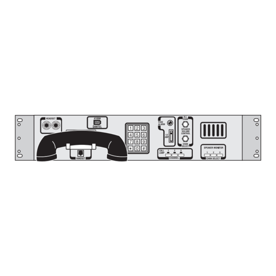
Speaker Monitor Panel with 1 DTSS3A Terminal (3-digit dialing) and 49921 Multi-Line Pick-up Key Subassembly C13-41096-32 Speaker Monitor Panel with 2 DTSS3A Terminals (3-digit dialing) and 49921 Multi-Line Pick-up Key Subassembly C13-41096-71 Speaker Monitor Panel with 1 DTSS3A Terminal (3-digit dialing) and 49924 Auxiliary Port Subassembly 41096-0597 <90-00042>... -
Page 3: General Description
GENERAL DESCRIPTION ♦ ♦ ♦ ♦ ♦ ♦ ♦ ♦ ♦ ♦ ♦ ♦ A - S 41096 C ABLE TANDARD ONFIGURATIONS MODEL PANEL DTSS3A 3-DIGIT 6-DIGIT 49921 49924 41096-0597 <90-00042>... -
Page 4: Circuit Description
CIRCUIT DESCRIPTION 41096-0597 <90-00042>... - Page 5 CIRCUIT DESCRIPTION . 1 - 41096 F UNCTIONAL CHEMATIC (P2) RCV T HEADSET XMT T - LAMP + LAMP HOOK SWITCH (P3) RCV T XMT T D I A L - LAMP XMT R + LAMP RCV R RCV T...
-
Page 6: Installation
BLANK PANEL CHANNEL 1 OPTION - 01 OPTION - 00 CHANNEL 3 CHANNEL 2 CHANNEL 2 CHANNEL 1 CHANNEL 1 CHANNEL 1 CHANNEL 1 CHANNEL 1 CHANNEL 1 OPTION - 02 ALT. POS. CH. 3 OPTION - 03 41096-0597 <90-00042>... - Page 7 INSTALLATION 2. Set the straps. B - S ABLE TRAP PTIONS STRAP POSITION CONTROL LIMIT BYPASS CHAN SELECT DTSS3A O NSTALLATION ONTO XISTING RDER ERMINALS 1. Remove mounting brackets. 2. Position 41096 Panel mounting brackets. 41096-0597 <90-00042>...
- Page 8 . 3 - M OUNTING RACKET TTACH NGLE OSITIONS SIDE VIEW SIDE VIEW FRONT FRONT VIEW VIEW FRONT FRONT "19 STANDARD MOUNT "19 FLUSH MOUNT SIDE SIDE VIEW VIEW FRONT FRONT VIEW VIEW FRONT FRONT "23 FLUSH MOUNT "23 STANDARD MOUNT 41096-0597 <90-00042>...
- Page 9 NOTE: If the telephone jacks J5, J6, and/or J7 are used to connect the 41096 to the Order Wire(s), two jumpers must be placed at the rear of each DTSS3A Order Wire to enable the monitor panel lamps to work. Install a jumper between pins P1-5 and P3-2 and another jumper between pins P1-7 and P3-1 on the back of the DTSS3A Order Wire.
- Page 10 RCV - T DTSS3A RCV - R XMT - T XMT - R J5 P2 41096 LAMP (-) LAMP (+) PANEL J6 P3 TO 2ND DTSS3 J7 P4 TO 3RD DTSS3 WIREWRAP TERMINAL PINS TYPICAL P1 - P4 41096-0597 <90-00042>...
-
Page 11: Operation
INSTALLATION 6. Install the assembled unit into the rack. 7. Connect supply leads. 8. Connect input and/or output ports. 9. Set the straps. OPERATION 41096-0597 <90-00042>... -
Page 12: Technical Specifications
TECHNICAL SPECIFICATIONS DESCRIPTION VALUE 41096-0597 <90-00042>... - Page 13 NOTES 41096-0597 <90-00042>...
-
Page 14: Warranty
4. Connections between Dantel’s equipment and your equipment. 1-800-4DANTEL (1-800-432-6835). 1-800-4DANTEL Dantel, Inc. • 2991 North Argyle Avenue • Fresno, California 93727-1388 P.O. Box 55013 • Fresno, CA 93747-5013 Phone (209) 292-1111 Fax (209) 292-9355 http://www.dantel.com 41096-0597 <90-00042> 14 P AGES...


Need help?
Do you have a question about the 41096 and is the answer not in the manual?
Questions and answers