Advertisement
Quick Links
About this Practice:
This practice has been reissued to:
• Update the 46113 strapping
options in the Installation section.
Reissued Practices: Updated and
new content can be identified by a
banner in the right margin.
Issue date: February 1999
Copyright 1999 by Dantel, Inc. • Dantel is a registered trademark of Dantel, Inc. • ISO 9001 Registered
46112 SynchMaster
D
C
ATA
ONTROLLER
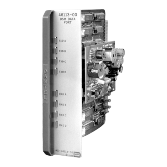
46113 SynchMaster
D
ATA
Table of Contents
Ordering Information ........................................................................... 2
General Description .............................................................................. 2
Circuit Description ............................................................................... 2
Application Information ....................................................................... 6
Installation .......................................................................................... 11
Operation ............................................................................................ 20
Technical Specifications ..................................................................... 21
Warranty ............................................................................................. 22
CAUTION
•
Install or remove modules from the shelf only when the power is off.
If you install a module in the shelf with the power on, the internal
circuitry may suffer damage and the product warranty will be void.
•
Remove and install circuit boards only in a static-safe environment
(use antistatic wrist straps, smocks, footwear, etc.).
•
Keep circuit boards in their antistatic bags when they are not in use.
•
Do not ship or store circuit boards near strong electrostatic, electromag-
netic, magnetic, or radioactive fields.
•
For more complete information on electrostatic discharge safety
precautions, refer to Bellcore
Printed in the U.S.A.
I
NSTALLATION
46112/113-0299 <90-00032>
M
P
M
ORT
ODULE
TM
Technical Reference # TR-NWT-000870.
& O
M
PERATION
ANUAL
ODULE
Advertisement

Related Manuals for Dantel SynchMaster 46112


Summary of Contents for Dantel SynchMaster 46112
-
Page 1: Table Of Contents
For more complete information on electrostatic discharge safety Issue date: February 1999 precautions, refer to Bellcore Technical Reference # TR-NWT-000870. Copyright 1999 by Dantel, Inc. • Dantel is a registered trademark of Dantel, Inc. • ISO 9001 Registered Printed in the U.S.A. -
Page 2: Ordering Information
ORDERING INFORMATION NOTE: This section lists the different options available for this product. To order any of the avail- able options, contact Dantel Inside Sales through our toll-free number, 1-800-432-6835. OPTION NUMBER FEATURES B11-46112-00 SynchMaster Data Controller Module SynchMaster Data Port Module... - Page 3 CIRCUIT DESCRIPTION 46112 SynchMaster D ONTROLLER ODULE The 46112 SynchMaster Module consists of: RS-422 Drivers and Receivers The RS-422 drivers and receivers are on a subassembly board that mounts on the main PC board. The RS-422 drivers and receivers provide data signal transformation from the module’s internal TTL data bus to the specific parameters of the RS-422 interface.
- Page 4 CIRCUIT DESCRIPTION Configuration Straps When the unit initially powers The configuration straps set the line clock polarity. When you up, the TX REPEAT LED blinks set the straps in the POS position, data changes at the rising on and off at a one second inter- edge of the clock pulse signals.
- Page 5 CIRCUIT DESCRIPTION 46113 SynchMaster D ODULE The 46113 SynchMaster Data Port Module consists of: RS-232 and RS-422 Drivers and Receivers The RS-232 and RS-422 drivers and receivers transmit and receive drop side data in their respective formats. The receivers transform the data to the TTL levels for use by the UARTs. Terminating Resistors The RS-422 inputs have strap enabled terminating resistors that operate the same as the 46112 SynchMaster module terminat-...
-
Page 6: Application Information
46113 SynchMaster Data Port Module for interfacing digital transmission equipment (such as fiber optic terminals, microwave equipment, and so on) and asynchronous transmis- sion equipment (such as Dantel’s 460 Alarm and Control Sys- tem). Fig. 3 shows a terminal mode application. Fig. 4 shows pin-for- pin wiring of the terminal mode application. - Page 7 APPLICATION INFORMATION . 3 - T ERMINAL PPLICATION DIGITAL TRANSMISSION FACILITY EQUIPMENT TERMINAL MODE APPLICATION 46112/113-0299 <90-00032>...
- Page 8 APPLICATION INFORMATION . 4 - T ERMINAL PPLICATION IRING FIBER OPTIC TERMINAL TXCI RXCI CLOCK DATA CLOCK DATA TRANSMIT RECEIVE (CLOCK IS INPUT) AUX CLOCK OUTPUT 46112 (REPEATER TXC0 MODE ONL Y) 36 38 39 40 EVEN NUMBERED NUMBERED PINS PINS 41 - 55 42 - 56...
- Page 9 APPLICATION INFORMATION . 5 - S IMPLE EPEATER PPLICATION DIGITAL DIGITAL TRANSMISSION TRANSMISSION WEST EAST EQUIPMENT EQUIPMENT TO OTHER TO OTHER PORTS PORTS REPEATER APPLICATION 46112/113-0299 <90-00032>...
- Page 10 APPLICATION INFORMATION . 6 - R EPEATER ERMINAL PPLICATION DIGITAL DIGITAL WEST TRANSMISSION TRANSMISSION EAST EQUIPMENT EQUIPMENT TO OTHER TO OTHER PORTS PORTS TERMINAL REPEATER APPLICATION 46112/113-0299 <90-00032>...
-
Page 11: Installation
INSTALLATION nstallation consists of setting the straps and switches, wiring the pin connectors, and mounting the module in the shelf. 1. Set the 46112 SynchMaster Module straps. Refer to Fig. 7. Each 46112 SynchMaster Module has two 2-position strapping points that configure the line clock polarity. The first two points are TXCPOL and RXCPOL. - Page 12 INSTALLATION . 7 - S , 46112 TRAP OCATIONS SUBASSEMBLY STRAPPING OPTIONS STRAPS POSITION X1, X2 and X3 RS422 INTERFACE SUBASS'Y . 8 - S , 46113 WITCH AND TRAP OCATIONS SUBASSEMBLY 1 2 3 4 5 1 2 3 4 5 6 7 8 STRAPPING OPEN OPEN...
- Page 13 INSTALLATION A - 46113 S ABLE WITCH ETTINGS FOR WITCHES ADDRESS SWITCH SETTING NOTE: DIP switch 1 for Port A, DIP switch 2 for Port B, DIP switch 3 for Port C and DIP switch 4 for Port D. Number CAUTION: Always set each port's address differently.
- Page 14 INSTALLATION B - 46113 S ABLE WITCH ETTINGS FOR WITCHES SWITCH FUNCTIONS (S5-1 to -8 = A, S6-1 to -8 = B, S7-1 to -8 = C, S8-1 to -8 = D) DESCRIPTION SWITCH SETTING MODE Terminal Repeater STOP BITS 1 Bit 2 Bits Data Bits...
- Page 15 INSTALLATION C - A ABLE LLOWABLE DDRESSES ERSUS SWITCH SETTINGS BAUD ALLOWED PORT PORT ADDRESSES NO (b/s) ADDRESS LONGER AVAILABLE 19.2K 2 thru 30, even numbered 19.2K 3 thru 31, odd numbered 9600 4, 8, 12, 16, 20, 24, 28 9600 5, 9, 13, 17, 21, 25, 29 9600...
- Page 16 INSTALLATION D - E ABLE XAMPLE DDRESS LLOCATION ABLE SWITCH SETTINGS ADDRESS PORT DESCRIPTION Port 1, 9600 Baud Port 2, 4800 Baud Port 3, 4800 Baud Port 4, 2400 Baud <Port 1> Port 5, 2400 Baud Port 6, 2400 Baud Port 7, 1200 Baud <Port 1>...
- Page 17 INSTALLATION E - B ABLE LANK DDRESS LLOCATION ABLE SWITCH SETTINGS ADDRESS PORT DESCRIPTION 46112/113-0299 <90-00032>...
- Page 18 INSTALLATION 4. Wire the pin connector. Wire the 46112 and 46113 SynchMaster Module connectors in the shelf. Refer to Figs. 9 and 10. 5. Install the modules in the shelf. Install the module in the proper equipment shelf slot by sliding the module along the guide slots, then firmly seating the edge connector.
- Page 19 INSTALLATION . 10 - P , 46113 ESIGNATIONS 46113 Card Edge Connector Pin Outs DATA ADDRESS (TO 46112) (TO 46112) XR/W XPORT XUART/SW XRST -BATT (-21 TO -56 VDC) MPI (RS 232) RS 232 PORT D RECEIVE RS 422 PORT D TRANSMIT RS 422 TD (RS 232) MPI (RS 232)
-
Page 20: Operation
OPERATION peration of the 46112 and 46113 SynchMaster Modules consists of observing the front panel LEDs. Refer to Figs. 11 and 12. 46112 Status indicating LEDs The 46112 SynchMaster Module’s green status indicating LEDs are designated as follows: ¨ RX SYNC The RX SYNC LED lights up when the When the unit initially powers 46112 SynchMaster Module receives frame information... -
Page 21: Technical Specifications
TECHNICAL SPECIFICATIONS DESCRIPTION VALUE Power Requirements Input Voltage (To 46113 Module Only) -21 to -56 VDC Current (in mA) -21 VDC -21 VDC -21 VDC -21 VDC 46113 (Alone) RS422 Interface Idle Active RS422 Interface Idle Active 46112 and 46113 Both RS422 Interface Idle Active... -
Page 22: Warranty
To ensure expedient processing of your order, provide a purchase order number and shipping and billing information when requesting an RMA number. Also, when the units are returned to Dantel, include a descrip- tion of the failure symptoms for each unit returned. Send defective equipment to: Dantel, Inc.
Need help?
Do you have a question about the SynchMaster 46112 and is the answer not in the manual?
Questions and answers