Advertisement
Quick Links
About this Practice:
This practice has been reissued to:
• Document B18 release with new
M Lead Interface Module.
• Update Figs. 2, 3, and 6.
Reissued Practices: Updated and
new content can be identified by a
banner in the right margin.
Issue date: November 1998
Copyright 1998 by Dantel, Inc. • Dantel is a registered trademark of Dantel, Inc. • ISO 9001 Registered
B18-05776-XX
U
O
RDER
A
Table of Contents
Ordering Information ........................................................................... 2
General Description .............................................................................. 2
Installation ............................................................................................ 3
Alignment Procedures .......................................................................... 9
Operation ............................................................................................ 15
Technical Specifications ..................................................................... 16
Warranty ............................................................................................. 18
CAUTION
•
Install or remove modules from the shelf only when the power is off.
If you install a module in the shelf with the power on, the internal
circuitry may suffer damage and the product warranty will be void.
•
Remove and install circuit boards only in a static-safe environment
(use antistatic wrist straps, smocks, footwear, etc.).
•
Keep circuit boards in their antistatic bags when they are not in use.
•
Do not ship or store circuit boards near strong electrostatic, electromag-
netic, magnetic, or radioactive fields.
•
For more complete information on electrostatic discharge safety
precautions, refer to Bellcore
Printed in the U.S.A.
I
NSTALLATION
NIVERSAL
W
SSEMBLY
TM
Technical Reference # TR-NWT-000870.
& O
M
PERATION
ANUAL
05776-1198 <90-00124>
IRE
Advertisement

Related Manuals for Dantel B18-05776 Series


Summary of Contents for Dantel B18-05776 Series
-
Page 1: Table Of Contents
For more complete information on electrostatic discharge safety Issue date: November 1998 precautions, refer to Bellcore Technical Reference # TR-NWT-000870. Copyright 1998 by Dantel, Inc. • Dantel is a registered trademark of Dantel, Inc. • ISO 9001 Registered Printed in the U.S.A. -
Page 2: Ordering Information
ORDERING INFORMATION NOTE: This section lists the different options available for this product. To order any of the avail- able options, contact Dantel Inside Sales through our toll-free number, 1-800-432-6835. OPTION NUMBER FEATURES B18-05776-00 Wired only. No modules B18-05776-01 Wired shelf equipped with one 46105 Dual VF 64Kb Channel module; one 44022 Subscriber Line Interface module;... -
Page 3: Installation
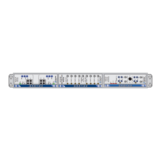
INSTALLATION his section consists of: ♦ Equipment mounting ♦ Wiring ♦ Switch and strap settings • 44118 Bridge • 44022 Subscriber Line Interface • 46105 Dual VF 64Kb Channel QUIPMENT OUNTING Install the shelf in an equipment rack using the hardware provided. - Page 4 INSTALLATION . 2 - F , 05776 S UNCTIONAL CHEMATIC HELF 05776-1198 <90-00124>...
- Page 5 INSTALLATION . 3 - R , 05776 S HELF C.O. Matching Adapt. Sub-Assembly With the reversing switches in the Installation Detail right, or NORM position (viewed from REVERSED SWITCHES CHANNEL 2 CHANNEL 1 the back), the associated idle output OUTPUT-WEST OUTPUT-EAST CHANNEL 1 CHANNEL 2...
- Page 6 INSTALLATION . 4 - S , 44118 B WITCH AND TRAP OCATIONS RIDGE B2X D2H B1X D1H HI LO HI LO HI LO HI LO LO HI HI LO B - S , 44022 S ABLE WITCH AND TRAP ETTINGS UBSCRIBER NTERFACE STRAP...
- Page 7 INSTALLATION . 5• - S , 44022 S TRAP OCATIONS UBSCRIBER NTERFACE XMT LEVEL ADJUST 44022-00 10dB STATION INTERFACE SIDE TONE Busy STATUS LED Inc. Call INDICATORS Off Hook PRIVACY TRANSMIT LINE TP LINE DISTRIBUTION OUTPUT TP REMOTE M LEAD DIST XMT DROP 2W/4W...
- Page 8 INSTALLATION . 6 - S , 46105 D VF 64K WITCH AND TRAP OCATIONS HANNEL CHANNEL 1 BRDG TERM RPTR LPBK 1 M LEAD 2 NO YES E LEAD TERM MODE RPTR DATA TERM CHANNEL S101 LPBK 2 05776-1198 <90-00124>...
-
Page 9: Alignment Procedures
ALIGNMENT PROCEDURES ll straps and levels are factory-set. If necessary, refer to the steps below to align the 44022, 44118, and 46105 modules. Equipment Required ♦ Signal Generator sending a 1kHz, 600 ohm signal at various levels. ♦ 600-ohm Level Meter (with and without 600-ohm termina- tion). - Page 10 ALIGNMENT PROCEDURES Read system test-tone level (+7 dBm). Adjust TRANSMIT level control as required. NOTE: Any source device that loads down the input must be disconnected. Disconnect the meter and test oscillator. Connect an A18-05775-00 Speaker/Monitor panel to the Universal assembly A18-05776-XX by using a 8 wire RJ 45 cable with no twists in the make-up of the cable.
- Page 11 ALIGNMENT PROCEDURES 44118 B RIDGE LIGNMENT ROCEDURE Refer to Fig 8. Remove power from the assembly . 8 - F , 44118 RONT ANEL Plug in the 44118 module. Apply power 44118-00 DISTRIBUTION Connect a 600-ohm terminated dB level meter across the 600-ohm BRIDGE output from the signal generator.
- Page 12 ALIGNMENT PROCEDURES Move signal generator to the LINE RCV PORT 1 jack (Jl). Do not readjust any receive level controls. Move the 600-ohm terminated dB level meter to the COMBINED DIST OUTPUT jack (J9). Read -10 dBm. Move the 600-ohm terminated dB level meter to the LINE XMT PORT 4 jack (J8).
- Page 13 ALIGNMENT PROCEDURES 46105 D VF 64K HANNEL LIGNMENT ROCEDURE Refer to Fig 9. To check the Audio Port Levels, other parts of the system do not have to be functioning. . 9 - F , 46105 RONT ANEL Set the loopback (LPBK) switches for both channels to the ON posi- tion.
- Page 14 ALIGNMENT PROCEDURES Remove the termination from the dB meter and verify a level of 0 dB at the front panel blue XMT LVL test points for both channels 1 and 2. Terminate the meter with 600 ohms and verify a level of +7 dB at the front panel RCV DROP jack of channel 1.
-
Page 15: Operation
ALIGNMENT PROCEDURES Hang up the handset and Pins 39 and 40 should go open. Use the other terminal 46105 and repeat the process for Channel 2 and check Pins 7 and 8. End of 46105 Alignment Procedure. OPERATION peration of the 05776 Universal Order Wire shelf, when used in conjunction with a 05775 Speaker Panel is simple and straight-forward. -
Page 16: Technical Specifications
TECHNICAL SPECIFICATIONS DESCRIPTION VALUE Input Voltage Range -21 to -56 VDC Input Power Requirement @ -24VDC Idle 164 mA Full Load 174 mA @ -48VDC Idle 85 mA Full Load 182 mA Heat Dissipation @ -24VDC Idle 23.2 BTU/Hr Full Load 46.2 BTU/Hr @ -48VDC Idle... - Page 17 NOTES 05776-1198 <90-00124>...
-
Page 18: Warranty
To ensure expedient processing of your order, provide a purchase order number and shipping and billing information when requesting an RMA number. Also, when the units are returned to Dantel, include a descrip- tion of the failure symptoms for each unit returned. Send defective equipment to: Dantel, Inc.
Need help?
Do you have a question about the B18-05776 Series and is the answer not in the manual?
Questions and answers