Advertisement
Quick Links
About this Practice:
This practice has been reissued to:
• Update Fig. 3.
Reissued Practices: Updated and
new content can be identified by a
banner in the right margin.
Issue date: July 1998
Copyright 1998 by Dantel, Inc. • Dantel is a registered trademark of Dantel, Inc. • ISO 9001 Registered
D
ATA
TERMINATION
Table of Contents
Ordering Information ........................................................................... 2
General Description .............................................................................. 2
Application Information ....................................................................... 2
Circuit Description ............................................................................... 3
Installation ............................................................................................ 6
Operation ............................................................................................ 14
Technical Specifications ..................................................................... 15
Warranty ............................................................................................. 16
CAUTION
•
Install or remove modules from the shelf only when the power is off.
If you install a module in the shelf with the power on, the internal
circuitry may suffer damage and the product warranty will be void.
•
Remove and install circuit boards only in a static-safe environment
(use antistatic wrist straps, smocks, footwear, etc.).
•
Keep circuit boards in their antistatic bags when they are not in use.
•
Do not ship or store circuit boards near strong electrostatic, electromag-
netic, magnetic, or radioactive fields.
•
For more complete information on electrostatic discharge safety
precautions, refer to Bellcore
Printed in the U.S.A.
I
NSTALLATION
44124
C
HANNEL
M
TM
Technical Reference # TR-NWT-000870.
& O
M
PERATION
ANUAL
44124-0798 <90-00024>
ODULE
Advertisement

Summary of Contents for Dantel 44124
-
Page 1: Table Of Contents
For more complete information on electrostatic discharge safety Issue date: July 1998 precautions, refer to Bellcore Technical Reference # TR-NWT-000870. Copyright 1998 by Dantel, Inc. • Dantel is a registered trademark of Dantel, Inc. • ISO 9001 Registered Printed in the U.S.A. -
Page 2: Ordering Information
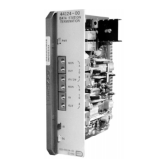
A loopback capability that can be activated manually or by a 2713 Hz tone ♦ Front panel LED indicators The 44124 DCTM is a plug-in printed circuit module that fits into any Dantel 400-type or similar equipment housing. It operates on -21 to -56 VDC input power. APPLICATION INFORMATION he 44124 is most often used in Dantel’s 460 Alarm and... -
Page 3: Circuit Description
460 ALARM AND CONTROL SYSTEM PORT CIRCUIT DESCRIPTION functional schematic for the 44124 Data Channel Termina- tion Module is shown in Fig. 2. Here is a brief description of each of the functional parts of the circuit: Impedance Matching Transformers... - Page 4 CIRCUIT DESCRIPTION . 2 - F , 44124 UNCTIONAL CHEMATIC 44124-0798 <90-00024>...
- Page 5 The output amplifier supplies up to 24 dB of gain or loss in 0.1 dB increments. Set the amplification level with switches S1 and S3. The amplified output signal couples to connector pins 41 and 47 and the XMT OUT jack contacts. 44124-0798 <90-00024>...
-
Page 6: Installation
LED indicates improper switching or reversed simplex lead polarity. Set simplex lead polarity with switch S5. Regulated Power Supply The regulated power supply furnishes all 44124 DCTM power requirements. It supplies sealing current when the source is -48 VDC. - Page 7 INSTALLATION . 3 - S , 44124 WITCH OCATIONS .1 .2 .4.8 1.5 3 6 12 OPEN 1 2 4 8 1 2 4 8 1 2 4 8 OPEN OPEN 150 600 1200 .1 .2 .4.8 1.5 3 6 12...
- Page 8 INSTALLATION ) - S , 44124 ABLE CONTINUED WITCH PTIONS & - - - 44124-0798 <90-00024>...
- Page 9 INSTALLATION . 4 - P , 44124 ESIGNATIONS RCV Input (Drop Side) TIP A/T2 Simplex RCV Input (Drop Side) RING XMT Output (Line Side) TIP XMT Output (Line Side) RING -21 to -56 VDC TEK 6 TEK 5 MLBG (Manual LoopBack Ground)
- Page 10 Insert the test cord into the RCV MON jack (refer to Fig. 5 for a 44124 DCTM front panel view). Record the cable losses (in dB) at the receive line end for the 404 Hz, 1004 Hz, 2504 Hz, and 3204 Hz frequencies.
- Page 11 2.60 2.20 2.90 2.35 3.10 2.50 3.25 2.60 3.60 2.65 4.00 2.70 4.15 2.75 4.30 2.80 4.45 2.85 4.60 NOTE: If the calculated values of Slope (SL) fall between settings, use the lower setting indicated by the table. 44124-0798 <90-00024>...
- Page 12 S7-4(8) (dB values) 0.00 0.35 1.05 1.75 2.45 3.15 3.85 4.55 5.25 5.95 6.65 7.35 8.05 8.75 9.45 10.15 NOTE: If the calculated values of Height (HT) fall between settings, use the lower setting indicated by the table. 44124-0798 <90-00024>...
- Page 13 ETTINGS FOR LOSS AT 2504 HZ WITH 1004 HZ FOR REFERENCE BW SETTING SWITCH Reference Total S7-5(1) S7-6(2) S7-7(4) S7-8(8) NOTE: If the calculated values of Bandwidth (BW) fall between settings, use the lower setting indicated by the table. 44124-0798 <90-00024>...
-
Page 14: Operation
♦ Set switch S12-3 to ON. ♦ Interconnect edge connector pins 1 and 19 (ground). The front panel of the 44124 DCTM has three LEDs (refer to Fig. 5): ♦ The green LED indicates applied power to the module. ♦... -
Page 15: Technical Specifications
TECHNICAL SPECIFICATIONS & & " 4 " 0 44124-0798 <90-00024>... -
Page 16: Warranty
To ensure expedient processing of your order, provide a purchase order number and shipping and billing information when requesting an RMA number. Also, when the units are returned to Dantel, include a descrip- tion of the failure symptoms for each unit returned. Send defective equipment to: Dantel, Inc.


Need help?
Do you have a question about the 44124 and is the answer not in the manual?
Questions and answers