Advertisement
Quick Links
About this Practice:
This practice has been reissued to:
• Add B11 designation to all refer-
ences of 48001-01.
Reissued Practices: Updated and
new content can be identified by a
banner in the right margin.
Issue date: October 1997
Copyright 1997 by Dantel, Inc. • Dantel is a registered trademark of Dantel, Inc. • ISO 9001 Registered
B11-48001-01
F
USE
Table of Contents
Circuit Description ............................................................................... 2
Ordering Information ........................................................................... 2
General Description .............................................................................. 2
Installation ............................................................................................ 5
Operation .............................................................................................. 9
Technical Specifications ..................................................................... 10
Warranty ............................................................................................. 12
CAUTION
•
Install or remove modules from the shelf only when the power is off.
If you install a module in the shelf with the power on, the internal
circuitry may suffer damage and the product warranty will be void.
•
Remove and install circuit boards only in a static-safe environment
(use antistatic wrist straps, smocks, footwear, etc.).
•
Keep circuit boards in their antistatic bags when they are not in use.
•
Do not ship or store circuit boards near strong electrostatic, electromag-
netic, magnetic, or radioactive fields.
•
For more complete information on electrostatic discharge safety
precautions, refer to Bellcore
Printed in the U.S.A.
I
& O
NSTALLATION
48001-1097 <90-00033>
M
ODULE
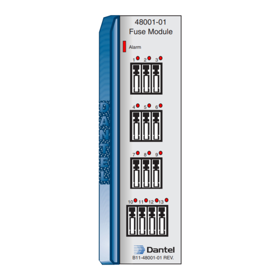
48001-01
Fuse Module
Alarm
1
2
3
4
5
6
7
8
9
10
11 12 13
B11-48001-01 REV.
Technical Reference # TR-NWT-000870.
TM
M
PERATION
ANUAL
Advertisement

Related Manuals for Dantel B11-48001-01


Summary of Contents for Dantel B11-48001-01
-
Page 1: Table Of Contents
For more complete information on electrostatic discharge safety precautions, refer to Bellcore Technical Reference # TR-NWT-000870. Issue date: October 1997 Copyright 1997 by Dantel, Inc. • Dantel is a registered trademark of Dantel, Inc. • ISO 9001 Registered Printed in the U.S.A. -
Page 2: Circuit Description
ORDERING INFORMATION NOTE: This section lists the different options available for this product. To order any of the avail- able options, contact Dantel Inside Sales through our toll-free number, 1-800-432-6835. OPTION NUMBER FEATURES B11-48001-01 Fuse Module GENERAL DESCRIPTION he B11-48001-01 Fuse Module provides 13 GMT indicating- type fuse circuits and a failure alarm circuit for fusing 400- type modules in an equipment shelf. - Page 3 CIRCUIT DESCRIPTION . 1 - F , B11-48001-01 F UNCTIONAL CHEMATIC ODULE FUSED OUTPUTS CIRCUITS -BATT. INPUT (GROUP 1) F1 THRU F6 EXT. FUSE FEED FUSED OUTPUTS CIRCUITS -BATT. INPUT (GROUP 2) F7 THRU F13 Kl * ALARM SYSTEM AS...
- Page 4 CIRCUIT DESCRIPTION A - JP1 S ABLE TRAP PTIONS POSITION DESCRIPTION Pins 1 & 2 Redundant or Single Input Pins 2 & 3 Two Independent Inputs JP1 strapped 1 & 2 ♦ Single Input Connecting one power supply to pins 35 and/or 36 or 31 and/or 32 supplies power to both fuse groups.
-
Page 5: Installation
28, bypassing any fuses. INSTALLATION he actual installation of this module is simple. To install the B11-48001-01 Fuse Module, place it in the proper slot in the equipment shelf. However, several factors deserve attention before installation:... - Page 6 AYOUT 48001-01 Fuse Module Alarm 11 12 13 B11-48001-01 REV. JP1 strapped 2 & 3 ♦ 2 independent supplies Connect one power supply to pins 35 and/or 36. This provides power to fuse group 1 (fuses 1 through 6). Connect a second power supply to pins 31 and/or 32.
- Page 7 INSTALLATION . 3 - B11-48001 E ONNECTOR ESIGNATIONS Fused Circuit 1 External Alarm Input Fused Circuit 2 External Alarm Input Fused Circuit 3 Fused Circuit 4 Fused Circuit 5 -Battery (Group 1) -Battery (Group 1) -Battery (Group 2) -Battery (Group 2) Fused Circuit 6 External Fuse Feed Fused Circuit 7...
- Page 8 10 yellow rivits, to indicate 0.18 amp fuses ♦ 10 violet rivits, to indicate 0.25 amp fuses Fuse ratings and their associated color codes, along with part numbers for fuses and rivits supplied by Dantel, are listed in Table B. B - F ABLE...
-
Page 9: Operation
To remove or replace a color-coded fuse rating rivit, follow these steps: ♦ Remove the B11-48001-01 module from the shelf and place it on a flat surface, component side up. ♦ Apply pressure to the back of the colored rivit, supporting the front panel with equal pressure from the front-side edge (to prevent bending it). -
Page 10: Technical Specifications
TECHNICAL SPECIFICATIONS - B11-48001 F ECHNICAL PECIFICATIONS ODULE DESCRIPTION VALUE Input Voltage Range -21 to -56 VDC Input Current @ -21 VDC Non-Alarmed 13 mA Alarmed 5 mA @ -56 VDC Non-Alarmed 20 mA Alarmed 10 mA Heat Dissipation @ -21 VDC Non-Alarmed 1.0 BTU/Hr Alarmed... - Page 11 NOTES 48001-1097 <90-00033>...
-
Page 12: Warranty
To ensure expedient processing of your order, provide a purchase order number and shipping and billing information when requesting an RMA number. Also, when the units are returned to Dantel, include a descrip- tion of the failure symptoms for each unit returned. Send defective equipment to: Dantel, Inc.
Need help?
Do you have a question about the B11-48001-01 and is the answer not in the manual?
Questions and answers