Table of Contents
Advertisement
Quick Links
Advertisement
Table of Contents

Related Manuals for Medifa 8000


Summary of Contents for Medifa 8000
- Page 1 800200 medifa 8000 Translation of the user manual Version: 4.0 EN...
-
Page 3: Table Of Contents
Product lifespan ......................16 Maintenance and repair ....................16 medifa 8000....................17 Proper and intended usage..................17 Intended users......................18 medifa 8000 and components..................18 Warning stickers on the medifa 8000................20 Connections and symbols .................... 21 Ratings plate........................ 22 medifa 8000... - Page 4 Foot switch (optional)....................47 6.4.1 Operation and functionality of the pedals ............48 Switching the medifa 8000 on and off............49 Establishing the equipotential bonding................ 50 Switching on and reactivating the medifa 8000............50 Switching off the medifa 8000 ..................51 Charging the medifa 8000 .................
- Page 5 Possible malfunctions and causes ................55 Transporting patients ................56 Notices on patient transport..................56 Transporting patients ....................57 Braking the medifa 8000 and releasing the brake ........58 Positioning the patient ................59 11.1 Preparing the medifa 8000 to hold the patient ............60 11.2...
- Page 6 Attaching and removing the cushions ................76 12.6.1 Attaching the cushions..................76 12.6.2 Removing the cushions ..................77 Preparing the medifa 8000 after it has been used ........78 13.1 Cleaning and disinfecting the medifa 8000..............78 13.1.1 Cleaning....................... 79 13.1.2...
-
Page 7: Important Information
MDR Annex I. The manufacturer also declares that the technical documentation has been implemented according to MDR Annex II. The manufacturer declares conformity by means of an EU Declaration of Conformity according to MDR Annex IV. Manufacturer and distributor medifa GmbH & Co. KG Industriestrasse 5 57413 Finnentrop Germany... -
Page 8: Copyright Notice
All rights under the copyright law are expressly reserved for medifa. medifa is only responsible for the safety characteristics within the scope of the statutory regulations if all maintenance, servicing and changes to this device have been carried out by the user or a representative as instructed. -
Page 9: Foreword
Foreword Foreword We at medifa thank you for purchasing the medifa 8000 X-ray OP table. The medifa 8000 is an X-ray OP table that combines design, functionality and comfort with the highest quality associated with German manufacturing. The medifa products are manufactured to have a long and trouble-free lifespan. The development, design and production at medifa have been certified to comply with DIN EN ISO 9001 and DIN EN ISO 13485. -
Page 10: Understanding These Operating Instructions
ATTENTION Please read and observe these operating instructions. These operating instructions must be read and fully understood by the operating personnel before the initial commissioning of the medifa 8000. This applies in particular to the Safety instructions and user chapter. -
Page 11: List Of Abbreviations
Understanding these operating instructions Chapter Content / topics ● Braking the medifa 8000 or releasing the brakes for driving Braking and releasing the brakes on the medifa 8000 ● Description of all functions for patient positioning and Positioning the patient position adjustment ●... -
Page 12: Symbols In Use
Understanding these operating instructions Symbols in use These operating instructions use various warning, notice and safety symbols to highlight information of particular relevance. Safety instructions DANGER DANGER indicates a hazardous situation which, if not avoided, will result in death or serious injury. WARNING WARNING indicates a hazardous situation which, if not avoided, could result in death or serious injury. -
Page 13: Safety Instructions And User Obligations
WARNING Danger for the patient! We cannot completely rule out the possibility of a malfunction of the medifa 8000 according to current state of the art technology. In this rare case, the motor-driven functions would no longer be available during the surgery. -
Page 14: Risk Of Explosion
Safety instructions and user obligations Risk of explosion There is a risk of explosion if the medifa 8000 is used under one or more of the following conditions: The following operating situations must absolutely be avoided within the AP-M zone: ●... -
Page 15: Electricity
Safety instructions and user obligations Electricity The electrical safety of the medifa 8000 and your power supply should be checked before first usage and regularly thereafter by a qualified electrician. We recommend that a general safety inspection be carried out yearly by medifa's technical support. -
Page 16: Product Lifespan
Safety instructions and user obligations Product lifespan The medifa 8000 has a lifespan of 10 years if the specified inspections are carried out by medifa service technicians. This does not apply to all wearing parts such as drives, controls, padded cushions or keys on the control units. -
Page 17: Medifa 8000
8000 Proper and intended usage The products described here are intended only for human medical purposes! The 800200 X-ray OP table, together with the other accessories from medifa, is intended only for the following uses: ● For supporting patients from the initiation of anaesthesia, during the operation, and until the end of anaesthesia. -
Page 18: Intended Users
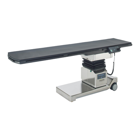
8000 and components The medifa 8000 X-ray OP table consists of a continuous carbon table plate. The control panel with joystick is located on the table top. An infra-red handset and a foot switch can also be configured to control the medifa 8000. - Page 19 8000 Features ● Control panel with colour display and built-in joystick ● Electrically conductive cushions (available in different thickness) ● Full carbon plate with built-in carbon standard guide rails for accessories ● Batteries and charger are built into table (with a capacity for approx. 1 week in normal operating mode).
-
Page 20: Warning Stickers On The Medifa 8000
Patients may not climb onto or sit in this area of t he table top. There is a risk of injury if the medifa 8000 is tilted The medifa 8000 may only be used on surfaces that have no more than a 5 degree tilt. Read the instructions before use. -
Page 21: Connections And Symbols
8000 Connections and symbols Figure 4: Symbols on the medifa 8000 Symbol Location Description Base Connection port for the foot switch Lifting column Connection port for the control panel Brake Foot brake released / engaged Base Connection for the equipotential bonding... -
Page 22: Ratings Plate
Specification for the battery fuse Lifting column (next to Follow the instructions! ratings plate) Ratings plate The ratings plate is located at the bottom of the lifting column of the medifa 8000. Connections and symbols, Page 21 medifa 8000 (01) 04250411XXXXXX... - Page 23 8000 Element / symbol Description Medical device Data matrix code AC 100 – 240 V Input voltage 24 V DC Battery voltage 50 – 60 Hz Frequency of the input voltage int. 1/9 min Intermittent operations: 1 min ON / 9 min OFF...
-
Page 24: Lifting Column
The lifting column includes: ● Column keypad ● Two infra-red receivers for the infra-red handset (optional) ● Connection port for the control panel ● Main switch of the medifa 8000 Figure 7: Lifting column with column keypad Translation of the user manual... - Page 25 8000 Figure 8: Main switch Figure 9: Connection port for the control panel Figure 10: Head-end infra-red receiver for the infra-red handset (optional) medifa 8000...
-
Page 26: Base
8000 Figure 11: Foot-end infra-red receiver for the infra-red handset (optional) Base The base includes: ● Manual chassis with electrically conductive rollers ● Pedal for the central brake ● Connection sockets for the mains power cable, equipotential bonding cable and foot switch ●... -
Page 27: Chassis
ATTENTION Do not use this product if the surface of the cushions is damaged. It is forbidden to use the medifa 8000 with unauthorized cushions; such usage would result in the loss of CE conformity. The cushioning can be disinfected and washed. It is also transparent for X-rays. The padded cushion is latex-free, breathable and anti-static. -
Page 28: Standard-Compliant Rails
5.12.1 Maximum permissible torques The maximum permissible torque on a standard rail of the medifa 8000 is 50 Nm on the lengthwise axis and 80 Nm on the transverse axis. The torque is acting on the rail as soon as an accessory is connected to a rail. -
Page 29: Internal And External Power Supplies
The weight of the patient's body part that will be resting on the accessory should be specified for mass (M). 5.13 Internal and external power supplies The medifa 8000 has an electronic system that monitors both the charging mode (the external power supply) and the charging state of the lead-gel rechargeable batteries (the internal power supply). medifa 8000... -
Page 30: External Power Supply
External power supply The external power supply for the medifa 8000 uses the mains power from a room (but not the surgery/ operating room). The medifa 8000 takes about 9 hours to fully charge. The charging current is reduced to a trickle charge current after the charging process is completed. -
Page 31: Battery Fuse
8000 is carried out. Switch off the main switch on the lifting column. Unscrew the cap of the external fuse in order to disconnect the medifa 8000 from the internal power supply. Remove the screw cap along with the fuse. The medifa 8000 is now disconnected from the internal power supply. -
Page 32: Standard Accessories
8000 5.14 Standard accessories For information on commonly used accessories, refer to the documentation that accompanies each accessory. Instructions for use of the following standard accessories are provided in this manual: Swivelling armrest ● Attaching and removing the swivelling armrest (article number 81220), Page 69 Turning/tilting armrest ●... -
Page 33: User Controls
Optional foot switch Column keypad The column keypad of the medifa 8000 is a control unit that is permanently mounted on the metal panel of the lifting column. The column keypad has backlit illumination. A simplified graphic of the medifa 8000 is shown on the column keypad. -
Page 34: Operation And Functionality Of The Keys
User controls 6.1.1 Operation and functionality of the keys Press down on the key Function is enabled Release the key Function is deactivated (thus immediately interrupting the procedure) SLIDE SLIDE Figure 18: Column keypad Symbol Name Function and operation Normal position disabled The normal position is disabled. - Page 35 Tilt the table top (at the lengthwise axis) to the left. Lateral left Lateral position (TILT RIGHT / TILT LEFT), Page 65 TILT RIGHT Tilt the table top (at the lengthwise axis) to the right. Lateral right Lateral position (TILT RIGHT / TILT LEFT), Page 65 medifa 8000...
- Page 36 79 – 20% capacity: working mode. The batteries are ready for use. Batteries are okay LED yellow Battery status: full 100 – 80% capacity: batteries are full. The medifa 8000 can be unplugged from the mains power supply and used in surgery. Battery full LED green LOAD No power cord is connected.
-
Page 37: Control Panel
User controls Control panel The control panel has backlit illumination. A simplified graphic of the medifa 8000 is shown on the control panel. All functions of the medifa 8000 can be executed from the control panel. They are displayed simultaneously on the display. The control panel has a colour display and a built-in joystick. - Page 38 Upwards height HEIGHT, Page 62 HEIGHT adjustment HEIGHT Moves the entire table top down. Downwards height This is the position for loading and unloading the patient, and adjustment for driving/moving the medifa 8000. HEIGHT, Page 62 Translation of the user manual...
- Page 39 The normal head position: The patient's head is at the head end of the table top. Normal position, Page 61 Reverse position The medifa 8000 is aligned in the reverse position: The patient's head is at the foot end of the table top. Reverse position, Page 62 Joystick Control lengthwise and sideways adjustments with the joystick.
-
Page 40: Save The Table Positions (Save)
8000 is in standby mode after it is switched on. 6.2.2 Save the table positions (SAVE) Press the SAVE key on the control panel to save a target position for the medifa 8000. This position can later be reached using the Memory key. Set the desired position. -
Page 41: Selecting A Saved Table Position (Memory)
The two keys for the user position are only available on the control panel. The shifting direction of the table top can be set using the user position key, so that it corresponds to the side of the medifa 8000 that the user is standing on. -
Page 42: Infra-Red Handset (Optional)
After 2 minutes, the handset goes into standby mode. The on/off switch is used to activate the handset. In order for a function to be carried out, the medifa 8000 must first be switched on at the control panel or column keypad. -
Page 43: Charging Station For The Infra-Red Handset
After the charging process is completed, the infra-red handset can be removed from the charging station. The charging station itself must then be disconnected from the mains power. Figure 21: Charging station and power plug for the infra-red handset medifa 8000... -
Page 44: Operation And Functionality Of The Keys
Display Name Function and operation handset Battery is empty: Display. < 20% capacity! Charge the battery immediately. Stop using the medifa 8000 and charge it. Recognizing the battery charging mode and charging status, Page 54 Battery status Display. normal: yellow 79 –... - Page 45 Name Function and operation handset Battery is full: Display. green 100 – 80% capacity: batteries are full. The medifa 8000 can be unplugged from the mains power supply and used in surgery. Adjustments are Display. locked. Further adjustments above 5 degrees for reverse Trendelenburg (REV.TREND) and sideways shifting (TILT...
- Page 46 HEIGHT Moves the entire table plate down. Downwards height This is the position for loading and unloading the patient, and adjustment for driving/moving the medifa 8000. HEIGHT, Page 62 SLIDE LEFT Sideways shift of the table top to the left.
-
Page 47: Foot Switch (Optional)
The three basic functions (Trendelenburg, height adjustment and lateral position) can be quickly selected using the optional foot switch. The foot switch is powered by the internal 5V power supply of the medifa 8000. Figure 23: Foot switch with 3 pedals... -
Page 48: Operation And Functionality Of The Pedals
Reverse Trendelenburg The medifa 8000 moves to the reverse Trendelenburg position and the function LED lights Lateral left The medifa 8000 tilts laterally to the left and the function LED lights up. Middle Downwards height adjustment The medifa 8000 is lowered and the function LED lights up. -
Page 49: Switching The Medifa 8000 On And Off
● Only use the medifa 8000 on an electrically conductive floor and with an equipotential bonding cable connected! ● The connection point for the equipotential bonding cable at the medifa 8000 complies with IEC 60601-1. -
Page 50: Establishing The Equipotential Bonding
8000. These control units are directly connected to the medifa 8000 and can reactivate the medifa 8000 from standby mode. Battery and charge indicators on the control panel and on the column keypad show that the medifa 8000 is charging when the power cable is connected. -
Page 51: Switching Off The Medifa 8000
Press the on/off switch on the control panel or on the column keypad. The lighting on the control units goes out. Switch off the main switch on the lifting column. There are certain situations where the medifa 8000 should be switched off using the main switch: ● Before a long downtime or pause ●... -
Page 52: Charging The Medifa 8000
DANGER Danger of electrocution and loss of life! – The medifa 8000 should be set up and positioned so that all plugs and device functions are easy to reach. – The medifa 8000 may only be connected to a power supply network that uses a cable with a protective earth conductor. - Page 53 Plug the power cable into table's power socket. Plug the power cable into a power outlet. Turn on the main switch at the lifting column of the medifa 8000. Look at the column keypad to check if the medifa 8000 is charging (the LOAD LED should be illuminated red).
-
Page 54: Recognizing The Battery Charging Mode And Charging Status
CAUTION Sparking in the AP-M zone can endanger your patient. If the battery status changes from yellow to red (under 20 % charge), the medifa 8000 must be taken immediately out of the surgery room and charged. There would otherwise be a risk to the patient due to batteries that are not ready for use or that are no longer functional. -
Page 55: Possible Malfunctions And Causes
Possible malfunctions and causes Problems and faults Cause Remedy The medifa 8000 cannot be The lead-gel batteries of the Connect the medifa 8000 to the switched on. medifa 8000 are completely power supply. discharged. The medifa 8000 cannot be The controller electronics, mains Notify the Technical Support charged. -
Page 56: Transporting Patients
The X-ray OP table can tip over when crossing over thresholds or bumps. – The medifa 8000 may only be moved or driven using two persons and when it is at its lowest height! CAUTION There is a risk of personal injury from being crushed! Be careful not to get your feet caught under the chassis when turning or moving the medifa 8000. -
Page 57: Transporting Patients
Move the table manually. Avoid jerky movements of the table. Check your surroundings when turning. Hold the table firmly while moving it. Use your hands to bring the table to a stop. Then brake with the brake pedal. medifa 8000... -
Page 58: Braking The Medifa 8000 And Releasing The Brake
Braking the medifa 8000 and releasing the brake CAUTION Danger for the patient Do not use the brake while you are driving the medifa 8000! Stop the medifa 8000 first. Bring the medifa 8000 to a halt. Press the brake pedal down. The medifa 8000 is now braked. -
Page 59: Positioning The Patient
WARNING Danger for the patient! We cannot completely rule out the possibility of a malfunction of the medifa 8000 according to current state of the art technology. In this rare case, the motor-driven functions would no longer be available during the surgery. -
Page 60: Preparing The Medifa 8000 To Hold The Patient
Preparing the medifa 8000 to hold the patient WARNING Any improper attachments pose a danger to the patient! Check all accessories to make sure that they are safely attached before using the medifa 8000! It is – possible for loose components to slip out of position. -
Page 61: Positioning Patients
Components which are under improper loads can break off from the medifa 8000 or cause the medifa 8000 to tilt. The patient may only get on or off in the area of t he lifting column! Sequence for adjusting to a desired patient position: First, use the height adjustment mechanism to set the desired working height. -
Page 62: Reverse Position
REVERSE POSITION key. After this, the table movements will be carried out correctly. After the medifa 8000 is switched off and back on, the normal patient position is always activated and displayed on the column keypad. -
Page 63: Trendelenburg/Reverse Trendelenburg (Trend/Rev.trend)
5 degrees. It is no longer possible to save positions which extend over 5 degrees. The 5 degree limit is signalled by a beep tone and a lock symbol shown on the display. medifa 8000... - Page 64 Positioning the patient CAUTION Danger to patients due to collision hazard! When tilting the table plate (Trendelenburg/reverse Trendelenburg), collisions can occur with the lifting column, floor or other objects that are located under the table plate and may be covered by cloths or pads.
-
Page 65: Lateral Position (Tilt Right / Tilt Left)
There is a risk of personal injury when the medifa 8000 is tilted. The medifa 8000 may only be used on surfaces that have no more than a 5 ° tilt. If the sideways shift is outside of the home position, the lateral adjustments are only permitted to 5 degrees. -
Page 66: Home Position (Level)
Positioning the patient 11.8 Home position (LEVEL) The home position is reached by automatically moving the medifa 8000 into a defined position. Position the accessories so that there is no risk of collisions during the movement to the home position. - Page 67 The lock symbol appears on the display SLIDE when lengthwise shifting is no longer possible on the head end. Lengthwise shifting at the foot end The lock symbol appears on the display SLIDE when lengthwise shifting is no longer possible on the foot end. medifa 8000...
-
Page 68: Sideways Shift (Slide Left / Slide Right)
Positioning the patient 11.10 Sideways shift (SLIDE LEFT / SLIDE RIGHT) For the sideways shift, the table plate is moved to the left or right side. The patient position can be set precisely, for example, by combining the Trendelenburg and lateral (up to 5 degree adjustment angle) adjustments. -
Page 69: Configuring The Medifa 8000
Configuring the medifa 8000 Configuring the medifa 8000 12.1 Information about the load limits The load limits are calculated using the following formula: Total weight (safe work load) = patient weight + accessory weight Refer to the chapter for the weights of individual accessories. -
Page 70: Adjusting The Swivelling Armrest
Configuring the medifa 8000 12.2.2 Adjusting the swivelling armrest Pull the release ball (located underneath) towards the user. Then turn the armrest to the desired position (it is adjustable up to 180 degrees). 12.2.3 Removing the swivelling armrest Press the clip-on retainer together. -
Page 71: Adjusting The Turn/Tilt Armrest
Configuring the medifa 8000 Press the clip-on retainer together and hook Release the clip-on retainer The mounting it (from top to bottom) into the carbon rail at block clamps firmly to the carbon rail. the desired position. 12.3.2 Adjusting the turn/tilt armrest Swivel the entire armrest out. - Page 72 Configuring the medifa 8000 Tighten the screw on the black handle clockwise. The position is now fixed. Adjusting the height of the armrest Hold the rod at the bend and turn the locking Move the armrest to the desired height and lever to the left to loosen the screw.
-
Page 73: Removing The Turn/Tilt Armrest
Configuring the medifa 8000 Turning and tilting the armrest Hold the armrest and loosen the grip slightly. Then, using the ball joint, tilt and turn the armrest to the desired position. 12.3.3 Removing the turn/tilt armrest Press the clip-on retainer together. Then tilt it If the retainer should remain on the rail, the slightly upwards and remove it. -
Page 74: Attaching And Removing The Side Extension (Article Number 81355)
Configuring the medifa 8000 12.4 Attaching and removing the side extension (article number 81355) Attaching the side extension Hook the side extension into the desired Tighten the knurled screw. position on the carbon rail from the top downwards. Removing the side extension Loosen the knurled screw. -
Page 75: Attaching And Removing The Side Support / Armrest (Article Number 81092)
Configuring the medifa 8000 12.5 Attaching and removing the side support / armrest (article number 81092) Attaching the side support Hook the product into the desired position on Move it to the desired position on the carbon the carbon rail from the top downwards. -
Page 76: Attaching And Removing The Cushions
Attaching the cushions ATTENTION Safety instructions Only use original cushions from medifa! – The patient should not be on the medifa 8000 when the cushions are not in place. – Do not place sharp objects in or on the cushions. – –... -
Page 77: Removing The Cushions
Configuring the medifa 8000 Place the cushion on the table top. Press it The cushion must be secured precisely on the down over a large area and check that it is table top. securely attached! 12.6.2 Removing the cushions Grab the edge of the cushion under one edge and pull it upwards. -
Page 78: Preparing The Medifa 8000 After It Has Been Used
ATTENTION Danger: incorrect maintenance may damage property! The medifa 8000 is not suitable for an automated cleaning process! Do not use a high-pressure cleaner! Due to the high pressure of the water jet, liquid could penetrate through gaps or joints and damage the device (through corrosion). -
Page 79: Cleaning
If parts are heavily contaminated, use concentrated cleaner and then wipe with clear water. For the cleaning, move the medifa 8000 to its highest table position and wipe with a damp cloth. In this position, the panels of the lifting column can be pulled apart so they are easy to clean. -
Page 80: Troubleshooting And Service - The We Care.code
You can also use the QR code to access product documentation (user manual, etc.) and send service requests directly to medifa. If your mobile phone's configured language is not yet available in the we care.Code system, English will be displayed. - Page 81 Troubleshooting and service – the we care.Code You may submit a service request directly to medifa if you cannot solve the problem by yourself. Tap on the < symbol in the From the Home screen, tap A window will open header bar.
-
Page 82: Technical Specifications
Technical specifications Technical specifications 15.1 Environmental conditions for the operation, storage and transport Temperature -20 °C to 50°C (storage/transport) +10 °C to +40 °C (operation) Relative humidity 10% to 95% (storage/transport) 20% to 80% (operation) Air pressure 70 kPa to 106 kPa (storage/transport) 80 kPa to 106 kPa (operation) 15.2 Dimensions, weights and load limits... -
Page 83: Adjustment Ranges
1 minute function execution followed by a 9 minute break without functioning Explosion protection Battery operations: Class AP Mains power supply: The medifa 8000 is not approved for use in potentially explosive atmospheres (AP-M)! Risk of explosion, Page 14 medifa 8000... -
Page 84: Emc Information
This can result in improper operation. – Portable RF communications equipment (radios, including their accessories such as antenna cables and external antennas) should not be used closer than 30 cm (12 inches) from the medifa 8000. Translation of the user manual... -
Page 85: Appendix
Danger: risk of personal injury when the medifa 8000 is tilted! – Use at least two people to carefully move the medifa 8000 from the wooden carton onto a flat place! ATTENTION Danger of damage to the electronics due to condensation! During transport, there is a risk of condensation which could damage electronic components. -
Page 86: Symbols On The Transport Packaging
Appendix 16.1.3 Symbols on the transport packaging There are several handling symbols on the transport packaging. Symbol Description +50 °C Temperature range for storage and transport: -20 °C to 50 °C. -20 °C 95 % Relative humidity for storage and transport: 10% to 95%. 10 % 106 kPa Air pressure for storage and transport: 70 kPa to 106 kPa. -
Page 87: Disposal
When not in use, switch off the medifa 8000 at the main switch. If the medifa 8000 has not been used for a long time, the batteries may not be fully charged. To prevent a battery malfunction or outage, the batteries must be charged each month during periods when the medifa 8000 is not being used. - Page 88 Appendix Product name Article number Weight (kg) Permissible load (kg) Head ring 61115 Body and leg strap 81405 Head support cushion 61147 Articulated arm with head cap 81110 DORO skull pin for adults 811073 0.25 DORO skull pin for children 811074 0.14 DORO skull clamp set...
- Page 89 Head pillow made of silicone gel for children 61911 Small half roller, made of silicone gel 61920 Medium half roller, made of silicone gel 61921 Half roller made of silicone gel 61922 Heel cushion made of silicone gel 61940 medifa 8000...
- Page 92 GmbH & Co. KG Industriestraße 5 57413 Finnentrop Germany fon +49 2721 71 77-0 fax +49 2721 71 77-255 info@medifa.com www.medifa.com...
Need help?
Do you have a question about the 8000 and is the answer not in the manual?
Questions and answers