Table of Contents
Advertisement
Quick Links
Advertisement
Table of Contents

Subscribe to Our Youtube Channel
Related Manuals for Medifa 63000 1 Series


Summary of Contents for Medifa 63000 1 Series
- Page 1 Extension device Article no. 63000_1, 63000_1SF User manual Version: 2.1...
-
Page 3: Table Of Contents
Table of contents Table of contents Important information............5 Revision history . - Page 4 Table of contents 11. Installation ..............18 11.1 Attaching the extension device to the operating table .
-
Page 5: Important Information
All rights according to the copyright law are expressly reserved by medifa. medifa shall only be responsible for the safety-related properties of this device within the framework of the legal regulations if maintenance, ser- vicing, and changes to this device are carried out by medifa itself or a representative in accordance with instruc- tions. -
Page 6: Understand The User Manual
Understand the user manual 2. Understand the user manual ATTENTION Read and follow the instructions in the user manual This user manual must be read and understood in full by the operating personnel before putting the extension device into operation; this applies in particular to the chapter on safety instructions and user obligations. If necessary, verified mediation by means of in-house training is also possible, taking into account the profes- sional qualifications. -
Page 7: Used Symbols
Used symbols 3. Used symbols Various information and safety symbols are used in this user manual to highlight particularly relevant information. Safety Instructions HAZARD HAZARD indicates an imminently hazardous situation which, if not avoided, will result in death or serious injury. -
Page 8: Safety Instructions And User Obligations
Safety instructions and user obligations 4. Safety instructions and user obligations Keep the user manual in the vicinity of the product so that information can be read at a later date. The user man- ual is an integral part of the product and must be handed over in case there is a change in location or personnel. Furthermore, the user manual must be easily accessible to all users of the product at all times. -
Page 9: Maintenance And Repair
For service work, please contact the medifa technical customer service department. Service life The product has a service life of 10 years if the specified inspection by medifa Service is observed. This excludes all wear parts and padding. User manual for extension device 63000_1 Version 2.1... -
Page 10: Intended Use
• medifa 6000 The extension device serves, in connection with the above-mentioned products and other medifa accessories, in the mounting, positioning and extension of the legs immediately before, during and after the execution of the surgical intervention, as well as for examination and treatment. -
Page 11: Type Label
Type label 6. Type label The type label is located under the mounting plate. medifa GmbH & Co. KG Industriestraße 5 , 57413 Finnentrop, Germany Extension device (11) xxxxx (01) 04250411523087 63000_1 xxxxx 05/2021 Figure 1: Type label Element / symbol... -
Page 12: Symbols Used
Symbols used 7. Symbols used On the transport packaging, there are various symbols related to handling. Element / symbol Description +50°C Temperature range for storage and transport -20 °C to 50 °C -20°C Relative humidity for storage and transport 10% to 95% 106 kPa Air pressure for storage and transport 70 kPa to 106 kPa 70 kPa... -
Page 13: Padding
ATTENTION Safety Instructions • Only use the original medifa padding! • Do not place the patient on the operating table system without padding. • Do not insert any sharp-edged objects into the padding or place them on the padding. -
Page 14: Model Description
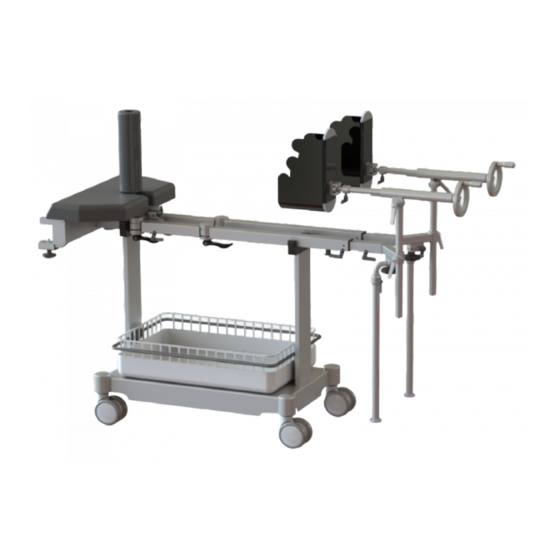
Model description 9. Model description Figure 2: Extension device No. Name Trolley with storage basket Docking element Swivelling longitudinal spar Swivelling and height-adjustable drawing spindles with adaption for extension shoe holders Extension shoe (accessories) Supporting bars User manual for extension device 63000_1 Version 2.1... -
Page 15: Assembly
Assembly 10. Assembly 10.1 Supplied individual parts for the equipment cart No. Name Quantity supplied Side spars Basket frame Plastic guide variant A Plastic guide variant B Storage basket Base with four mounted twin castors M8 screw for basket frame M10 screw for side spar M8 Washer for basket frame M10 Washer for side spar... -
Page 16: Symbols On The Transport Packaging
Assembly 10.3 Symbols on the transport packaging No. Name Quantity supplied Drawing spindle Supporting bars Longitudinal spar Docking element Countertraction post Extension shoe (optional) Figure 4: Extension device (exploded view) User manual for extension device 63000_1 Version 2.1... -
Page 17: Assembly Of Extension Device
Assembly 10.4 Assembly of extension device Figure 5: Structure of extension device Open the locking element [1] on the left and right spar [2] of the extension device. Place the left and right spar [2] on the spars of the docking element [3] and retighten both the locking ele- ments [1]. -
Page 18: Installation
Installation 11. Installation 11.1 Attaching the extension device to the operating table Push the extension device with trolley until just before the bottom part of the operating table. Adjust the height of the operating table to the height of the square bolts of the extension device. -
Page 19: Operation
Operation 12. Operation 12.1 General operation The left and right spars have a toothed joint which is adjustable in one plane, but the spars are still ad- justable vertically and horizontally. This is achieved by dismantling the spar and reassembling it at the surface rotated by 90°. -
Page 20: Drawing Spindle / Extension Shoe
Operation 12.3 Drawing spindle / extension shoe The extension shoe is mounted on the side of the shoe slot [1] and fixed by means of the locking element [2]. To dismantle the drawing spindle, the locking element [3] must be loosened. The extension shoe can be rotated by loosening the locking element [4], e.g. -
Page 21: Adjustment Options
Operation 12.4 Adjustment options 1. The adjustment range of the middle leg is 90°. The eccentric lever [3] must be loosened to adjust the spar in the horizontal or vertical plane. When the starting position is reached, the eccen- tric lever [3] must be fixed. 2. -
Page 22: Positioning Of Patient
CAUTION Patient hazard Incorrectly attached accessories can come loose and cause injury. Only use medifa accessories and fix the ac- cessories correctly. Use accessories from other manufacturers only after approval by medifa. User manual for extension device 63000_1 Version 2.1... -
Page 23: Care Instructions
Care instructions 14. Care instructions CAUTION Danger of personal injuries! • Only hand over cleaned and disinfected devices / equipment to a service technician for maintenance and repair work. • Replace padding that no longer meets the hygiene and infection prevention requirements. ATTENTION Risk of damage to property due to incorrect care. -
Page 24: Disinfectant Recommendation
• The composition of disinfectant agents corresponds to the information in March 2019. For any changes in the formulation of the disinfectants by the manufacturers, medifa GmbH & Co. KG cannot assume any guaran- tee. User manual for extension device 63000_1 Version 2.1... -
Page 25: Technical Data
Technical data 15. Technical data 15.1 Environmental conditions for operation, storage, and transport - 20°C to + 50°C (storage / transport) Temperature + 10°C to + 40°C (operation) 10 % to 95 % (storage / transport) Relative humidity 20 % to 80 % (operation) 70 kPa to 106 kPa (storage / transport) Air pressure 80 kPa to 106 kPa (operation) -
Page 26: Delivery, Unpacking And Installation
Delivery, unpacking and installation 16. Delivery, unpacking and installation The delivery takes place on a pallet in a carton. Ordered parts/accessories are individually packaged on the pallet or are attached to the product. Dimensions of the packaging Length 800 mm Width 600 mm Height... -
Page 27: Accessory List
Accessory list 17. Accessory list Product name Article number Permissible load (kg) Extension shoe for adults 61010 Extension shoe for children 61020 Countertraction post for femur 63025_1 Countertraction post for tibia and fibula 63045 Pelvis plaster cast unit 63030 Horseshoe holder 63060 Leg supports 63026... -
Page 28: Disposal
For proper disposal of old devices, please contact medifa's technical customer service department, your local dealer, or the appropriate national authority. The medifa company takes back old devices, defective or no longer used products. For detailed information, please contact medifa's technical customer service department. - Page 30 GmbH & Co. KG Industriestraße 5 57413 Finnentrop Germany Telephone +49 2721 7177-0 fax +49 2721 7177-255 info@medifa.com www.medifa.com...
Need help?
Do you have a question about the 63000 1 Series and is the answer not in the manual?
Questions and answers