Table of Contents

Related Manuals for Vitrek 4600A


Summary of Contents for Vitrek 4600A
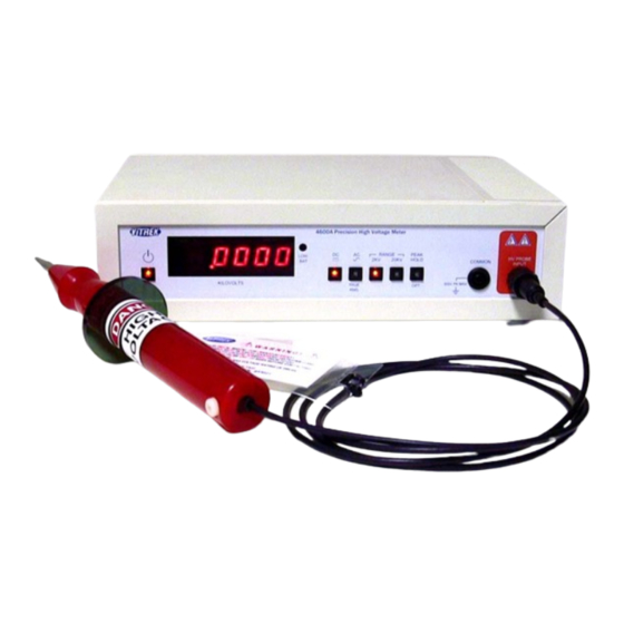
- Page 1 4600A Precision High Voltage Meter Operating Manual 9880A Via Pasar, San Diego CA 92126 USA V: (858)689-2755 F: (858)689-2760 Web: www.vitrek.com E-mail: info@vitrek.com Copyright Vitrek Corporation 2001, all rights reserved, rev 12/20/2001...
- Page 3 We will repair or replace the instrument under warranty, provided it is returned to Vitrek Corporation freight prepaid. No other warranty is expressed or implied. We are not liable for consequential damages. Permission and a return authorization number must be obtained directly from the factory for warranty repairs.
-
Page 5: Table Of Contents
TABLE OF CONTENTS _______________________________________________________________ SECTION I: UNPACKING AND INSTALLATION 1-1 Introduction 1-2 Inspection 1-3 Fuse Protection 1-4 Bench Use 1-5 Rack Mounting 1-6 Tips for Battery Option 1-7 Safety Precautions SECTION II: SPECIFICATIONS 2-1 Accuracy 2-2 DC Voltage Measurements 2-3 AC Voltage Measurements (True RMS) 2-4 General Specifications SECTION III: OPTIONAL EQUIPMENT 3-1 General... -
Page 7: Section I: Unpacking And Installation
1-3. Fuse Protection The Model 4600A uses two internal fuses, one to protect the main power supply from an over current condition and other protects the battery option from receiving an excessive charging current. Both fuses are the same type: 5 X 20mm, 250VAC, 1A slow-blo fuse. If either fuse is blown, it may indicate a problem with the internal power supply circuits. -
Page 8: Rack Mounting
1-5. Rack Mounting An optional kit is available for mounting the 4600A in a standard 19" equipment rack. This is listed in Section 3. Follow the installation instructions included with the option. If the 4600A is to be transported while mounted in a rack, it should be supported so as to prevent upward or downward movement. -
Page 9: Safety Precautions
Operators should be aware of general safety precautions for working with hazardous voltages and must always heed the following precautions: 1. Ensure that the 4600A is properly earth grounded either through its 3-wire power cord or via its rear panel ground terminal. When battery power is used without out power cord, you must connect rear panel ground terminal to earth ground. -
Page 10: Section Ii Specifications
SECTION II SPECIFICATIONS _______________________________________________________________ 2-1. Accuracy The accuracy specifications for the Model 4600A are valid for a period of 1 year from the date of calibration at 23˚C (±3°C). 2-2. DC Voltage Measurements Ranges: 2kV and 20kV Resolution: 100mV on 2.0000kV, 1V on 20.000kV ±0.04% of reading ±0.02% of range... -
Page 11: Section Iii Optional Equipment
3-1. General The Model 4600A is shipped with a 10” High Voltage probe with 6 ft lead, common lead, power cord, operating manual, and NIST traceable certificate of calibration. TL-20-46 High Voltage lead assembly terminated with a large alligator clamp in lieu of standard HV probe assembly. -
Page 12: Section Iv Operation
4-1. General This section provides complete operating instructions for the Model 4600A. The 4600A is a safe and reliable instrument when used in accordance with the operating instructions. However, High Voltage encountered while using this instrument may be hazardous or fatal! Please read all instructions thoroughly before attempting to operate the Model 4600A. -
Page 13: Making High Voltage Measurements
±500VDC or peak AC (relative to earth ground). Voltages greater than this may damage the unit. The other measurement terminal on the 4600A is the BNC style HV probe input terminal. The 4600A is calibrated to a specific HV probe. The probe is identified with a serial number tag which should match the serial number of the main 4600A unit. -
Page 14: Option "Peak Hold" Operation
This may be seen as a condition in which the 4600A will not respond to any input in any range, and the display may wander around aimlessly. This condition is temporary and will correct itself within 30 seconds after removal of the input voltage. -
Page 15: Section V Routine Maintenance
_______________________________________________________________ 5-1. General This section provides general maintenance information and a procedure for calibrating the voltmeter. The Model 4600A should be calibrated on a routine basis (every 12 months is recommended) to ensure continued accuracy. 5-2. Required Test Equipment The test equipment listed below or its equivalent is required for performance of the calibration procedure. -
Page 16: Battery Replacement Instructions
5-4. Battery Replacement Instructions The rechargeable battery assembly used in the 4600A consists of three PCB mounted 2-volt cells. The cells are of the sealed lead-acid type, and should provide years of trouble-free service. The replacement battery assembly is available as Vitrek Stock 947-1000. The battery assembly should always be replaced as a complete assembly.
Need help?
Do you have a question about the 4600A and is the answer not in the manual?
Questions and answers