Table of Contents
Advertisement
Quick Links
Advertisement
Table of Contents

Subscribe to Our Youtube Channel
Related Manuals for Vitrek 4700


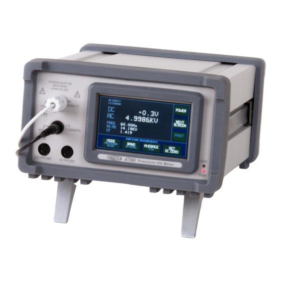
Summary of Contents for Vitrek 4700
- Page 1 ViTREK 4700 OPERATING & MAINTENANCE MANUAL...
-
Page 2: Table Of Contents
4700 Operating Manual - May 28, 2015 About this Manual ................................. 7 Warranty Information ..............................8 SECTION 1 – PRODUCT INFORMATION.......................... 9 Features ..................................9 Available Options and Accesories ..........................9 Interfacing Options ..............................9 Terminal Options ..............................9 Power Options ............................... 9 Probe Accessories .............................. - Page 3 Measurement Time ..............................24 SECTION 5 – Using the 4700 ............................25 4700 Rear Panel Switches ............................25 SHIP Switch ................................25 AUTO ON Switch ..............................25 4700 Front Panel CHG and PWR Indicators ......................25 Page 3 of 55...
- Page 4 POWER Button ..............................34 NEXT SCREEN Button ............................34 PRINT Button ............................... 34 Configuring the Interfaces and Power Consumption of the 4700 ................34 CHANGE INTERFACE Button ..........................35 SETUP LAN Button ............................... 35 SELECT BAUD RATE Button ..........................35 SET GPIB ADDR Button ............................
- Page 5 Controlling the 4700 by the LAN Interface ......................38 Specifications ............................... 38 Connections ................................. 39 Printing from the 4700 using the USB Interface ...................... 39 Specifications ............................... 39 Connecting ................................39 SECTION 7 – PROGRAMMING VIA AN INTERFACE ....................... 40 LOCAL and REMOTE Operation ..........................
- Page 6 4700 Operating Manual - May 28, 2015 Calibration of a 4700 and Probe(s) .......................... 49 Adjustment Calibration (4700) ..........................49 Adjustment Calibration (PROBE) ......................... 51 Verifying Calibration (4700) ..........................52 Verifying Calibration (PROBE) ..........................54 Page 6 of 55...
-
Page 7: About This Manual
4700 Operating Manual - May 28, 2015 ABOUT THIS MANUAL This applies to all 4700 instruments having a main firmware revision of 1.10; there may be minor differences if the 4700 being operated has a different main firmware version. Due to continuing product refinement and possible manufacturer changes to components used in this product, ViTREK reserves the right to change any or all specifications without notice. -
Page 8: Warranty Information
Any recommendations made by ViTREK or its representatives, for uses of its products are based on tests believed to be reliable, but ViTREK makes no warranties of the results to be obtained. This warranty is in lieu of all other warranties, expressed or implied and no representative or person is authorized to represent or assume for ViTREK any liability in connection with the sale of our products other than set forth herein. -
Page 9: Section 1 - Product Information
Option GP-47 adds a GPIB interface to the standard RS232, LAN and USB printer interfaces. TERMINAL OPTIONS Option RPO-47 changes the terminals to be on the rear panel instead of on the front panel as in a standard 4700. POWER OPTION S Option BP-47 adds an internal Lithium-Ion battery pack to the 4700. -
Page 10: Probe Accessories
4700 Operating Manual - May 28, 2015 PROBE ACCESSORIES Any of the following probes can be used with the 4700. All probes are calibrated for use with any 4700. Two probes can be used for differential measurements. HVP-35. This is a hand held probe allowing measurements up to 35KV. -
Page 11: Section 2 - Safety
WARNING - THE 4700 MEASURES VOLTAGES WHICH MAY BE LETHAL; UNSAFE OPERATION MAY RESULT IN SEVERE INJURY OR DEATH. WARNING - IF THE 4700 IS USED IN A MANNER NOT SPECIFIED BY VITREK, THE PROTECTION PROVIDED BY THE EQUIPMENT MAY BE IMPAIRED AND SAFETY MAY BE COMPROMISED. -
Page 12: Section 3 -Installation, Storage And Shipping
Mains Measurement Measurement Category I THE 4700 SHOULD NOT BE USED IN AN ENVIRONMENT WHERE CONDUCTIVE POLLUTION CAN OCCUR, E.G. IN AN OUTDOOR ENVIRONMENT. IF FLUIDS OR OTHER CONDUCTIVE MATERIALS ARE ALLOWED TO ENTER THE UNIT ENCLOSURE, EVEN IF NOT POWERED, THEN THE UNIT SHOULD BE IMMEDIATELY TAKEN OUT OF OPERATION AND SERVICED AS SAFETY MAY HAVE BEEN COMPROMISED. -
Page 13: Shipping And Storage
The 4700 has a rear panel accessible switch (labeled SHIP) which totally disables the 4700 during shipment if this switch is placed in the down position. If a 4700 with option BP-47 is to be shipped or is to be stored for periods of longer than several days then placing this switch in the down position will prevent the 4700 from being accidently turned on in transit and will also reduce the self-discharge rate of the battery. -
Page 14: Section 4 - Input Specifications
Vitrek during calibration of the 4700 and probes; to obtain the accuracy relative to the standards and methods used in the actual calibration of the 4700 or probes reduce all DC accuracy specifications by 0.0075% of reading and all AC accuracy specifications by 0.025% of reading. -
Page 15: Input Impedance
3.025MΩ ± 2% in parallel with <10pF to the 4700 chassis ground DIRECT:COMMON MEASUREMENT SPECIFICATIONS This section contains the specifications for the 4700 when not using an external probe (i.e. the 4700 is measuring the voltage between the DIRECT and COMMON terminals of the 4700). -
Page 16: High Voltage Self-Heating
HVP-35 OR HVL-35 HI PROBE:COMMON MEASUREMENT SPECIFICATIONS This section contains the specifications for the 4700 when using a single HVP-35 or HVL-35 probe (i.e. the 4700 is measuring the voltage between the HI PROBE tip and COMMON terminal of the 4700). These specifications assume that no signal is present on the DIRECT terminal. -
Page 17: Measurement Resolution
4700 Operating Manual - May 28, 2015 MEASUREMENT RESOLUTION Measurement resolution is dependent on the HI PROBE tip voltage (AC content only in RIPPLE mode). DC & AC 0.01V (<800Vpk±10%), 0.1V (<8KVpk±10%), 1V (otherwise) Limited to a maximum of 6 digits (5 digits in RIPPLE and FAST modes) Pk-Pk 0.1V (<800Vpk±10%), 1V (<8KVpk±10%), 10V (otherwise) -
Page 18: High Voltage Self-Heating
HVL-70 HI PROBE:COMMON MEASUREMENT SPECIFICATIONS This section contains the specifications for the 4700 when using a single HVP-70 or HVL-70 probe (i.e. the 4700 is measuring the voltage between the HI PROBE tip and COMMON terminal of the 4700). These specifications assume that no signal is present on the DIRECT terminal. -
Page 19: Probe Location
4700 Operating Manual - May 28, 2015 PROBE LOCATION Full accuracy specifications are valid assuming that there are no objects within a cylinder of radius 24” centered on the probe body extending from the handle (or base) to a point 9” beyond the probe tip. The connection to the probe tip is assumed to extend from the probe tip in line with the probe for at least 9”. -
Page 20: High Voltage Self-Heating
HVL-70G HI PROBE:COMMON MEASURE MENT SPECIFICATIONS This section contains the specifications for the 4700 when using a single HVL-70G probe (i.e. the 4700 is measuring the voltage between the HI PROBE tip and COMMON terminal of the 4700). These specifications assume that no signal is present on the DIRECT terminal. -
Page 21: Hvl-100 Hi Probe:common Measurement Specifications
HVL-100 HI PROBE:COMMON MEASURE MENT SPECIFICATIONS This section contains the specifications for the 4700 when using a single HVL-100 probe (i.e. the 4700 is measuring the voltage between the HI PROBE tip and COMMON terminal of the 4700). These specifications assume that no signal is present on the DIRECT terminal. -
Page 22: High Voltage Self-Heating
HVL-100G HI PROBE:COMMON MEASURE MENT SPECIFICATIONS This section contains the specifications for the 4700 when using a single HVL-100G probe (i.e. the 4700 is measuring the voltage between the HI PROBE tip and COMMON terminal of the 4700). These specifications assume that no signal is present on the DIRECT terminal. -
Page 23: Hvl-150 Hi Probe:common Measurement Specifications
HVL-150 HI PROBE:COMMON MEASURE MENT SPECIFICATIONS This section contains the specifications for the 4700 when using a single HVL-150 probe (i.e. the 4700 is measuring the voltage between the HI PROBE tip and COMMON terminal of the 4700). These specifications assume that no signal is present on the DIRECT terminal. -
Page 24: Hi Probe:lo Probe Measurements
4700 Operating Manual - May 28, 2015 HI PROBE:LO PROBE MEASUREMENTS These specifications assume that no signal is present on the DIRECT or COMMON terminals. Add the relevant HI PROBE : COMMON accuracy specifications for each probe (each in volts using the voltage on each probe in the computation), for AC measurements also add the AC Common Mode Error from the table below as a percentage of the LO PROBE AC voltage. -
Page 25: Section 5 - Using The 4700
SHIP SWITCH This switch totally disables the 4700 during shipment if it is in the down position. If a 4700 with option BP-47 is to be shipped or is to be stored for periods of longer than several days then placing it in the down position will prevent the 4700 from being accidently turned on in transit and will also reduce the self-discharge rate of the battery. -
Page 26: Using The 4700 Touchscreen
TURNING ON THE 4700 After ensuring that power is applied to the 4700 either via the rear panel DC power input or via the internal batteries if option BP-47 is fitted, the unit may be turned on by pressing and holding the front panel touchscreen (typically it must be continuously held for at least 250ms to turn the 4700 power on). -
Page 27: Making Measurements With The 4700
If a probe is in use as either the HI or LO terminal then the type of probe is shown at the top of the screen. If the probe is being used with the 4700 which was the calibration host for this probe, then HOST is displayed along with the type of probe. -
Page 28: Operating Manual - May
The 4700 probes are high impedance probes, as with any such probe they will pick up fields present in the area of the probe yielding a non-zero AC indication when no apparent input is applied. Such fields are always present unless the 4700 is being used in a very sparsely populated area with no local mains supply, or in a shielded environment. -
Page 29: Measurement Results
DC subtracted signal. The starting and ending zero crossings are automatically selected in the 4700 to be approximately one measurement time apart, independently of the amplitude results measurement time. The frequency measurement is used to “lock” the measurement time to an integer number of cycles of the applied signal, so fully synchronous DC and AC measurements are made. -
Page 30: Band Button
For measurements of DC and mains frequencies (or higher) the 30-600Hz setting is recommended. The BAND selection has a large effect on the measurement time and on the amount of time the 4700 takes to “lock-on” to a signal when initially applied or changed; see MEASUREMENT TIME in SPECIFICATIONS for details. -
Page 31: Set Dc Zero Button
PRINT – READY. This indicates that a suitable printer is properly attached to the 4700 USB printer port and that it is ready to print. Pressing this button causes the 4700 to print a short page containing the present measurement results and a listing of the measurement configuration. -
Page 32: Result Button
4700 Operating Manual - May 28, 2015 The 4700 can collect DC and AC measurement results over a user configurable time span. Starting data collection can be performed either manually or automatically. The measurement results are configured on the Primary Measurement Results Screen. -
Page 33: Time Span Button
– START – MANUAL The 4700 immediately starts collecting data for the chart. The chart is updated as data is collected and the user may stop data collection using the STOP button while data is being collected. -
Page 34: Power Button
PRINT – READY. This indicates that a suitable printer is properly attached to the 4700 USB printer port and that it is ready to print. Pressing this button causes the 4700 to print a single page containing the present chart (in monochrome) and a listing of the measurement and chart configuration. -
Page 35: Change Interface Button
4700 to connect to your LAN, you will need to know if DHCP can be used (typically this is fine, but some LANs do not allow it) and if not then an IP address for the 4700, a gateway IP address and the local subnet mask for the LAN. -
Page 36: Set Gpib Addr Button
The screen backlight has a typical life of several thousand hours; this can be extended by turning off the backlight when the 4700 screen is left inactive for a period of time. Also, if option BP- 47 is fitted this can save power during periods of inactivity. -
Page 37: Maintaining The 4700 Batteries (Option Bp-47)
The batteries can be degraded if the 4700 is left in storage for long periods of time. If it is planned to take the 4700 out of service for periods of more than a few days, or if the 4700 is to be shipped, then it is recommended to place the rear panel accessible SHIP switch in the DOWN position to prevent degradation of the batteries and also prevent the possibility of the 4700 being accidently turned on. -
Page 38: Section 6 - Connecting Interfaces
CONTROLLING THE 4700 BY THE GPIB INTERFACE CONNECTIONS Using a standard GPIB cable connect the GPIB port on the 4700 rear panel to the GPIB port of a computer. It is recommended to use a high quality, shielded GPIB cable. Cables may be purchased from ViTREK. -
Page 39: Connections
HP LaserJet 2420. The 4700 is generally not compatible with multi-purpose printers (e.g. “All-in-One” types). CONNECTING The printer should be connected to the 4700 USB Printer port using a standard USB cable of any suitable length. The printer must be directly connected to the 4700; a hub must not be used. -
Page 40: Section 7 - Programming Via An Interface
4700 to LOCAL operation. If the 4700 has been enabled to return to the local state by the controlling interface then the standard set of buttons will return if this is pressed. -
Page 41: Field Syntax
1023 characters. The 4700 does not raise an error if an empty set of commands is received, i.e. if there are two or more consecutive command terminators. This is effectively a “do nothing” set of commands. -
Page 42: Field Separator
<NR3>. This is a string of characters defining a floating point numeric value, optionally having a polarity, and/or a decimal point, and/or an exponent. Within the limitations of the 4700 command input buffer, there is no limitation on the number of numeric characters before the decimal, after the decimal or in the exponent. -
Page 43: Delays And Timeouts
On the GPIB interface the user must take some action to receive the response from the 4700 (i.e. a READ bus operation). If a read operation is performed when there is no data to be transmitted then a blank data is transmitted (i.e. -
Page 44: Interface Clear (Ifc)
4700 has become off-line and restart the session. If a session is inactive for more than 1 minute then the 4700 will allow a session to be initiated from a different source, automatically closing the inactive session if a new session is started. This prevents a potential lockup if the user does not close an active session properly. -
Page 45: Opc Register
4700 Operating Manual - May 28, 2015 Bit 6, decimal value 64, binary value 01000000 – as defined by IEEE488.1, set if the 4700 is asserting the SRQ line, otherwise it is cleared. Always zero for the SRE register. -
Page 46: Commands
6. The command contained additional fields than expected. 7. The command keyword was not recognized. 8. The 4700 had an internal memory error while executing the command. 9. The previous response had not yet been transmitted when this query command was executed. - Page 47 4700 Operating Manual - May 28, 2015 Command Description Configuration Settings Query Commands Responds with a <STRING> corresponding to the present MODE setting (PRECISE, MODE? FAST20, FAST16 or RIPPLE) Responds with a <NR1> corresponding to the present display resolution limit...
- Page 48 4700 Operating Manual - May 28, 2015 Command Description Responds with a set of <STRING> fields describing the product field : VITREK field : 4700 *IDN? field : Main firmware revision field : 2 firmware revision field : 3 firmware revision Misc.
-
Page 49: Section 8 - Performance Verification And Adjustment
4700, and using a probe with the 4700 which was used for calibrating the probe. If both a 4700 and probe(s) are to be calibrated together then the 4700 must be calibrated first, and then the probe should be calibrated with that 4700. - Page 50 These are available from ViTREK. PROCEDURE Follow the prompts in the display of the 4700 for the actual procedure as changes may be made in future releases of the 4700 firmware to enhance accuracy. 1. On the Configuration Screen, press the CALIBRATE key.
-
Page 51: Adjustment Calibration (Probe)
HVL-100 a frequency of 100Hz should be used. PROCEDURE Follow the prompts in the display of the 4700 for the actual procedure as changes may be made in future releases of the 4700 firmware to enhance accuracy. Page 51 of 55... -
Page 52: Verifying Calibration (4700)
12169, but this may be changed by the user (contact ViTREK for details regarding how to do this). 4. Press the ADJUST PROBE key on the screen. 5. As requested on the screen of the 4700, provide the requested voltage to the tip of the probe and perform the requested adjustments, note the following- Avoid excessive movement around the calibration area, particularly when calibrating HVL-100 or any HVL-xxG series probes. - Page 53 5MΩ value plus 24.99KΩ. 6. An 8-pin Mini-DIN connector suitable for plugging into the PROBE 1 and 2 inputs to the 4700 front panel. These are available from ViTREK.
-
Page 54: Verifying Calibration (Probe)
4700 Operating Manual - May 28, 2015 PROCEDURE Follow the prompts in the display of the 4700 for the actual procedure as changes may be made in future releases of the 4700 firmware to enhance accuracy. 1. On the Configuration Screen, press the CALIBRATE key. - Page 55 AC reading when the probe input is shorted to the COMMON terminal of the 4700 may be used as an indication. As previously described in this manual, the AC zero cannot be subtracted from the displayed results. The user will need to take corrective action if the zero indication is too high.
Need help?
Do you have a question about the 4700 and is the answer not in the manual?
Questions and answers